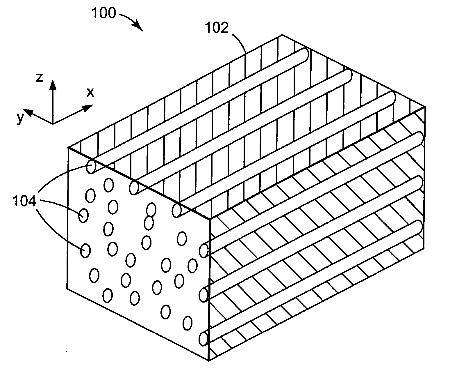
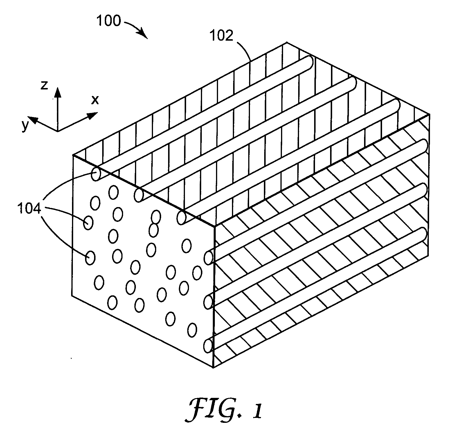
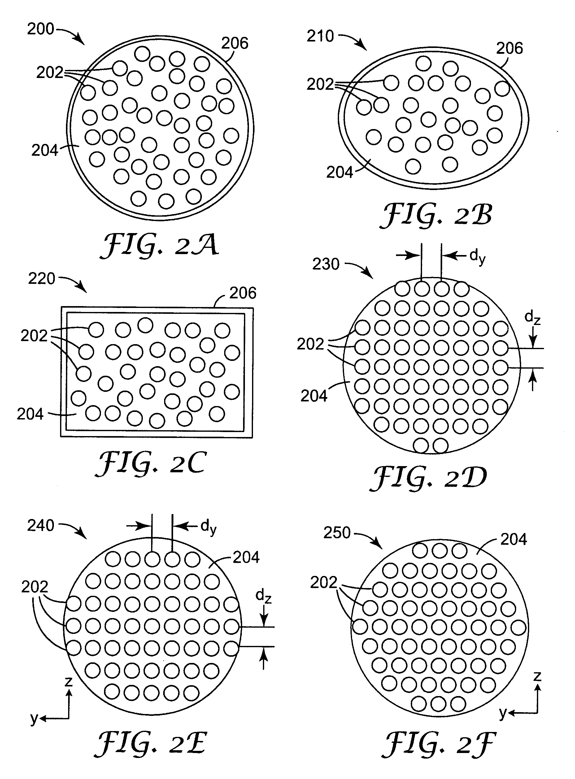
Composite polymer fibers

a polymer fiber and composite technology, applied in the field of polymer fibers, can solve the problems of high cost of devices, unreliable optical fibers, and insufficient penetration of photonic crystal devices into the marketpla

Active Publication Date: 2006-08-31
3M INNOVATIVE PROPERTIES CO
View PDF76 Cites 52 Cited by
  • Summary
  • Abstract
  • Description
  • Claims
  • Application Information

AI Technical Summary

Problems solved by technology

Photonic crystal devices have not yet, however, experienced significant penetration into the marketplace.
One of the reasons for this is the difficulty in fabricating photonic crystal fibers, which makes these devices expensive.

Method used


Image

  • Composite polymer fibers
  • Composite polymer fibers
  • Composite polymer fibers

Examples


example

[0129] In an example of coextruding a composite fiber, a feedblock having one hundred and eighteen laser-machined plates and eleven end-milled plates, was assembled. The feedblock also included two input ports and about 1000 “island” output ports. The feedblock was designed to achieve scattering fibers that have substantially equal polymer flow. A cross-section through the resulting coextrudant composite fiber is shown in the photograph in FIG. 13. The composite fiber comprised a PEN (90%) / PET (10%) copolymer as the scattering fiber “islands” in a filler “sea” of a PETG copolyester, Eastar™ 6763, supplied by Eastman Chemical Co., Kingsport, Tenn. The extruded composite fiber is about 200 μm in diameter. The composite fiber was not stretched but, with stretching while maintaining geometric shape, could reach a diameter of around 25 μm, i.e., a reduction in diameter of around 87%. At such a stretch, the spacing between the scattering fibers would be about 500 nm. The cross-sectional d...


PUM

PropertyMeasurementUnit
refractive indexaaaaaaaaaa

Abstract

A composite polymer fiber comprises a polymer filler material and a plurality of polymer scattering fibers disposed within the filler material. At least one of the filler material and the scattering fibers is formed of a birefringent material. The refractive indices of the filler material and the scattering fibers can be substantially matched for light incident in a first polarization state on the composite polymer fiber and unmatched for light incident in an orthogonal polarization state. The scattering fibers may be arranged to form a photonic crystal within the composite fiber. The composite fibers may be extruded and may be formed into a yarn, a weave or the like. If the filler material is soluble, it may be washed out of the yarn or weave, and the scattering fibers may then be infiltrated with a resin that is subsequently cured.

Description

RELATED APPLICATIONS [0001] This application is related to co-owned U.S. patent application Ser. ______, titled “REFLECTIVE POLARIZERS CONTAINING POLYMER FIBERS”, filed on even date herewith, having attorney docket no. 58959US002; ______, titled “COMPOSITE POLYMERIC OPTICAL FILMS WITH CO-CONTINUOUS PHASES”, filed on even date herewith and having attorney docket no. 60401US002; ______ titled “OPTICAL ELEMENTS CONTAINING A POLYMER FIBER WEAVE”, filed on even date herewith and having attorney docket no. 60622US002; ______ titled “POLYMER PHOTONIC CRYSTAL FIBERS”, filed on even date herewith and having attorney docket no. 60623US002; and ______, titled “POLYMERIC PHOTONIC CRYSTALS WITH CO-CONTINUOUS PHASES”, filed on even date herewith and having attorney docket no. 60624US002, all of which are incorporated herein by reference.FIELD OF THE INVENTION [0002] The invention relates to polymer fibers, and more particularly to “island in the sea” polymer fibers formed as photonic crystals. BA...

Claims


Application Information

Patent Timeline
Patent Type & Authority Applications(United States)
IPC IPC(8): G02B6/036G02B6/02G02B6/10B29D11/00G02B6/00
CPCD01D5/36D01F8/14G02B1/045G02B5/3008G02B6/001G02B6/0051G02B6/0053G02B6/02347G02B6/02352G02B6/02357G02B6/02361G02B6/02371G02B6/024G02B6/04G02B1/04G02B6/02G02B6/036
Inventor OUDERKIRK, ANDREW J.BENSON, OLESTER JR.BREISTER, JAMES C.BROTT, ROBERT L.CHOU, YEUN-JONGFLEMING, PATRICK R.KOPECKY, WILLIAM J.NORTH, DIANESTUMO, ROGER J.THUNHORST, KRISTIN L.WILSON, BRUCE B.
Owner 3M INNOVATIVE PROPERTIES CO
Why Eureka
Try Eureka