Drilling element for a bearingless rotor

a technology of bearingless rotors and drilling elements, which is applied in the direction of liquid fuel engines, vessel construction, marine propulsion, etc., can solve the problems of unfavorable warpage of cross section profiles, and excessive swinging of joints of rotor blades to rotor heads, so as to achieve low torsional stiffness, high swinging stiffness, and high twisting strength

Inactive Publication Date: 2006-08-31
AIRBUS HELICOPTERS DEUT GMBH
View PDF4 Cites 7 Cited by
  • Summary
  • Abstract
  • Description
  • Claims
  • Application Information

AI Technical Summary

Benefits of technology

[0009] The twist element according to the invention has a very high swing stiffness and, at the same time, a low torsional stiffness and twist stiffness as well as a high torsional strength and twist strength. When rotated, it is largely warpage-free. The twist element according to the invention has a relatively compact overall cross section while, at the same time, exhibiting a high strength. The twist element according to the invention is thus especially well-suited for tilt rotor applications. Since the twist element according to the invention, as mentioned above, is very rotation-flexible, then at a given rotational angle range, it can also be configured so as to be considerably shorter than prior-art twist elements. The length of the twist element according to the invention can be reduced to about one-third of the length of a conventional, prior-art twist element. This, in conjunction with the compact overall cross section, in turn, translates into considerable aerodynamic advantages: during the operation of the rotor, the total air resistance of the twist element is reduced and the proportion of the rotor radius length that is gained through the possible shortening of the twist element can be used as an aerodynamically effective rotor area of the rotor blade. This, in turn, reduces the total resistance of the rotor and improves its aerodynamic characteristics.

Problems solved by technology

Due to the H-shaped cross section as well as the great spread of the legs of the Y-shaped cross section, an unfavorable warpage of the cross section profile can occur when the twist element is subjected to torsion.
Due to the above-mentioned shape of the cross section as well as the great spread of the flanges or arms, an unfavorable warpage of the cross section profile can occur when the twist element is subjected to torsion.
If the conventional twist elements were to be used in unchanged form for such an application purpose, this would cause the joint of a rotor blade to a rotor head to be too swing-flexible.
Moreover, the strength of the twist element would no longer be adequately ensured.
However, if the prior-art twist elements were designed so as to be sufficiently swing-stiff and stable, then the twist elements—due to the resultant excessively high torsional stiffness or twist stiffness—would no longer be adequately rotatable, which can have a detrimental effect especially on the controllability of a rotor equipped with such a twist element.
Furthermore, such a twist element would be quite heavy and would have a very large overall diameter, which is undesirable from an aerodynamic standpoint as well as with an eye towards keeping the empty weight of a rotorcraft as low as possible.
Finally, the prior-art twist elements are also very long, which is a drawback from an aerodynamic point of view since the total air resistance of the twist element is quite high and moreover, a relatively large area of the radius of the rotor cannot be used as an aerodynamically effective area of the rotor blade.

Method used


Image

  • Drilling element for a bearingless rotor
  • Drilling element for a bearingless rotor

Examples


Embodiment Construction

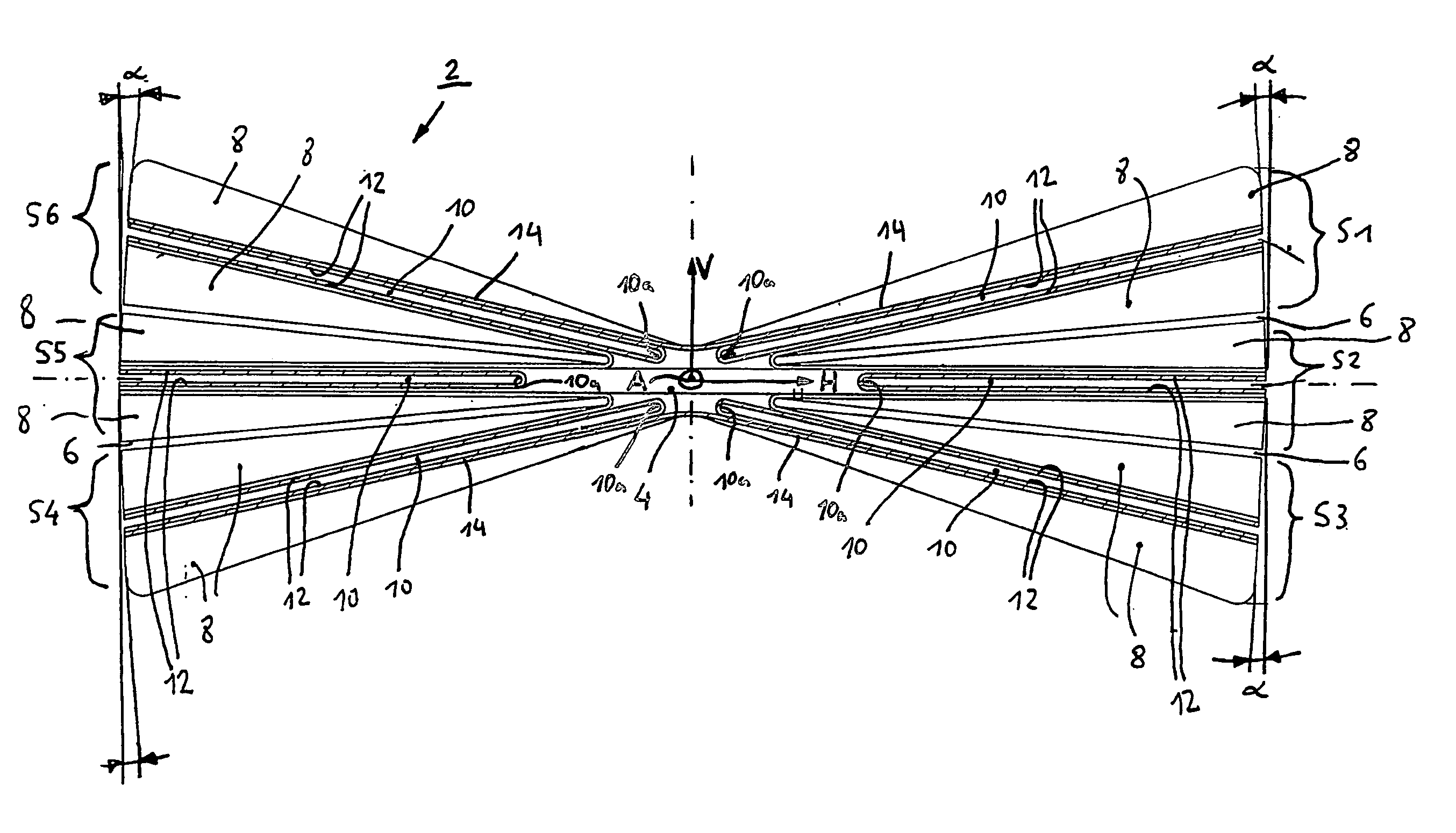
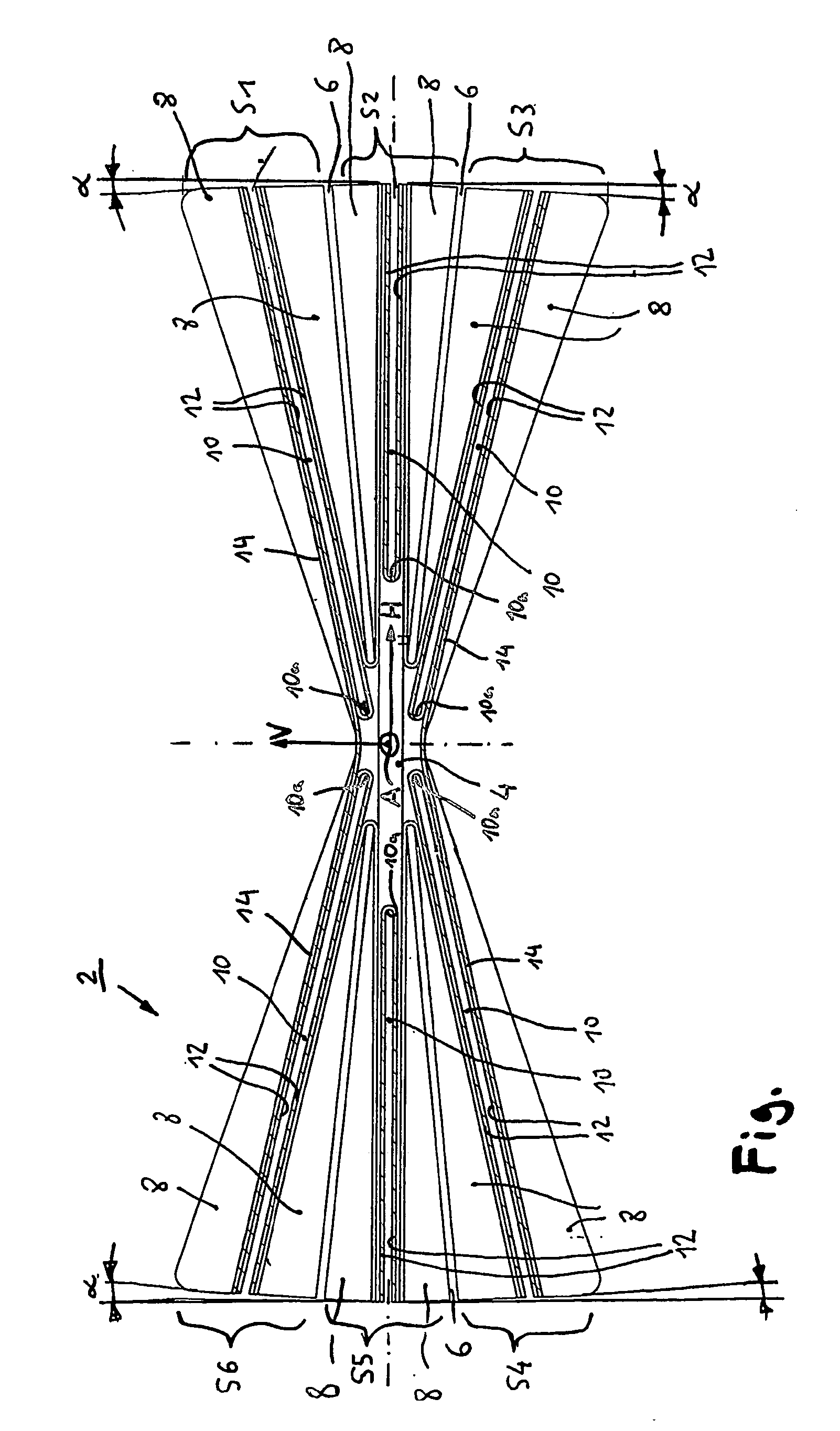
[0015] The figure shows a schematic cross sectional depiction of a twist element 2 for a bearingless rotor. The twist element 2 according to the invention is made predominantly of composite fiber material. As can be clearly seen in the drawing, said twist element 2 has a symmetrical, flattened cross section that has approximately the contour shape of a horizontal section through the center of a double cone. The horizontal center axis of the cross section of the twist element is designated with the reference letter H and the vertical center axis with the reference letter V. It can also be said that the contour of the cross section of the twist element has approximately the shape of two relatively narrow, horizontal, essentially isosceles triangles that are oriented symmetrically with respect to the horizontal and vertical center axes H, V and that are joined together in the area where their tips face each other. This contour or cross section is almost completely filled up by composit...


PUM


Abstract

A twist element for a bearingless rotor is made mostly of composite fiber material and has a cross section with a substantially symmetric, flattened shape that has approximately the contour of a horizontal, central section of a double cone. In addition, a bearingless rotor having at least one such twist element. and a rotorcraft, particularly a helicopter, having at least one rotor with at least one such twist element are provided.

Description

FIELD OF THE INVENTION [0001] The present invention relates to a twist element for a bearingless rotor. Furthermore, the invention relates to a bearingless rotor having such a twist element as well as to a rotorcraft, particularly a helicopter, having such a rotor. DESCRIPTION OF RELATED ART [0002] European patent application 0 323 857 B1 discloses a bending plate to be installed on a rotor mast, comprising a rotor mast attachment section, a rotor blade attachment section that is arranged at one free end of the bending plate and that is in the form of two bushings as well as a swing-flexible and torsion-flexible intermediate area that is situated between the rotor mast attachment section and the rotor blade attachment section and that forms a twist element. The twist element has an approximately H-shaped cross section that is formed by a centered, strip-shaped element and by two elements arranged laterally thereto, each of which has a cross section in the shape of a horizontal Y. Th...

Claims


Application Information

Patent Timeline
Patent Type & Authority Applications(United States)
IPC IPC(8): B64C27/46B64C27/33
CPCB64C27/33
Inventor DENECKE, ULRICHKUNTZE-FECHNER, GERALDBANSEMIR, HORSTEMMERLING, STEFAN
Owner AIRBUS HELICOPTERS DEUT GMBH
Why Eureka
Try Eureka