Pulley for clutchless compressor

a clutchless compressor and pulley technology, applied in the field of pulleys, can solve the problems ofconsiderable pulley manufacturing costs, and achieve the effects of reducing pulley manufacturing costs, eliminating time-wasting manufacturing steps in the related art, and eliminating time-wasting processes

Inactive Publication Date: 2006-08-31
VALEO SYST THERMIQUES
View PDF0 Cites 11 Cited by
  • Summary
  • Abstract
  • Description
  • Claims
  • Application Information

AI Technical Summary

Benefits of technology

[0006] Accordingly, an object of the present invention is to reduce the pulley manufacturing costs by eliminating the time wasting processes when bonding the elastic member.
[0007] In order to achieve the object described above, the present invention provides a pulley for a clutchless compressor, comprising a hub unit fixed to a drive shaft of the compressor and a damper unit disposed between a member that rotates in response to a drive force imparted from a drive source and the hub unit to achieve a buffer effect via an elastic member thereof, characterized in that the hub unit and the damper unit are formed as separate members independent of each other and that it includes an engaging means for engaging the hub unit and the damper unit to each other.
[0008] According to the present invention, the hub unit and the damper unit, which are initially manufactured as separate members, are integrated later via the engaging means, thereby forming a single damper assembly. Since this eliminates the need to strip the paint coated on the hub unit when bonding the elastic member as in the related art, the time wasting manufacturing step in the related art is eliminated, which, in turn, lowers the pulley manufacturing cost.

Problems solved by technology

The considerable pulley manufacturing costs are in part attributable to such a time wasting procedure.

Method used


Image

  • Pulley for clutchless compressor
  • Pulley for clutchless compressor
  • Pulley for clutchless compressor

Examples


embodiment 1

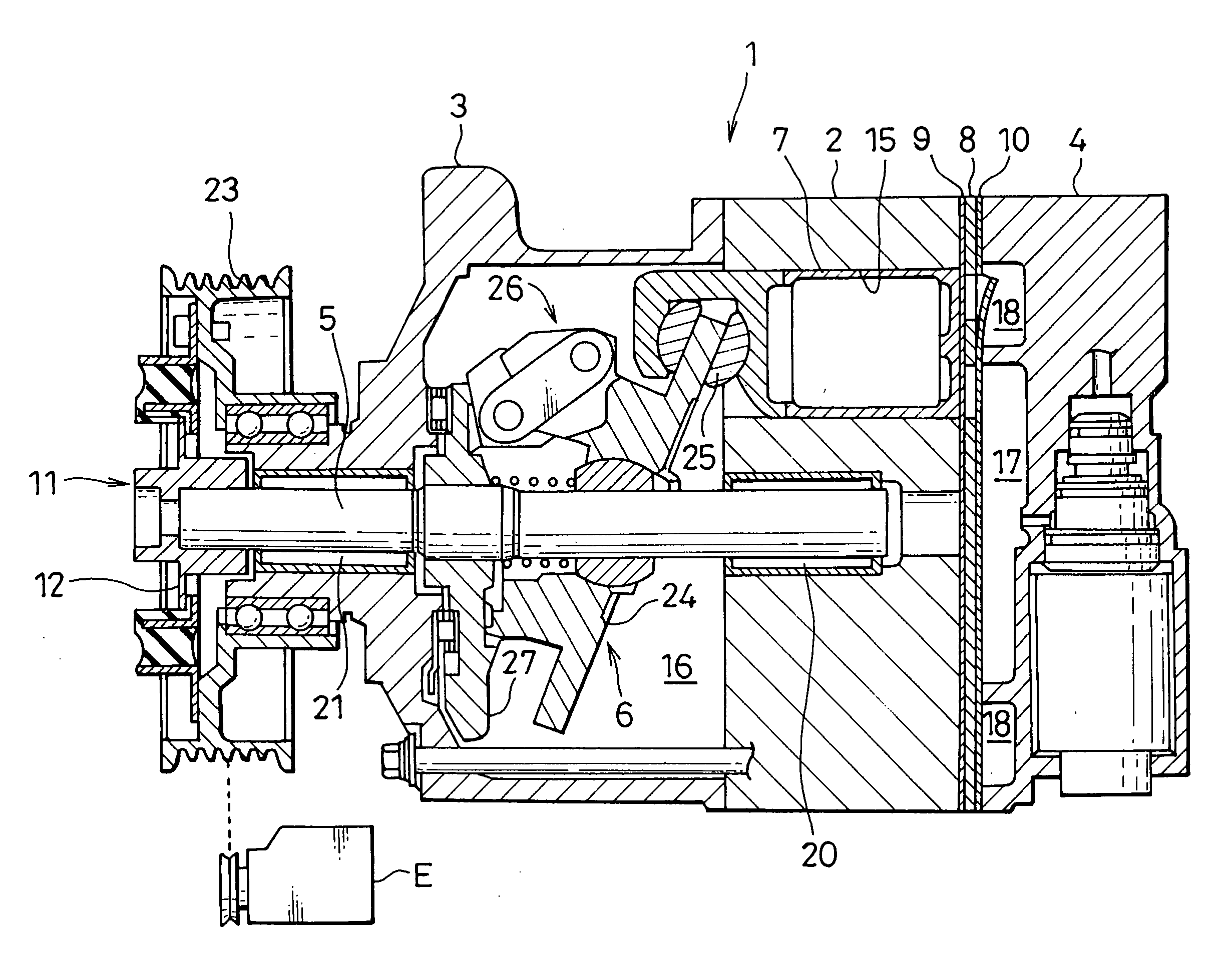
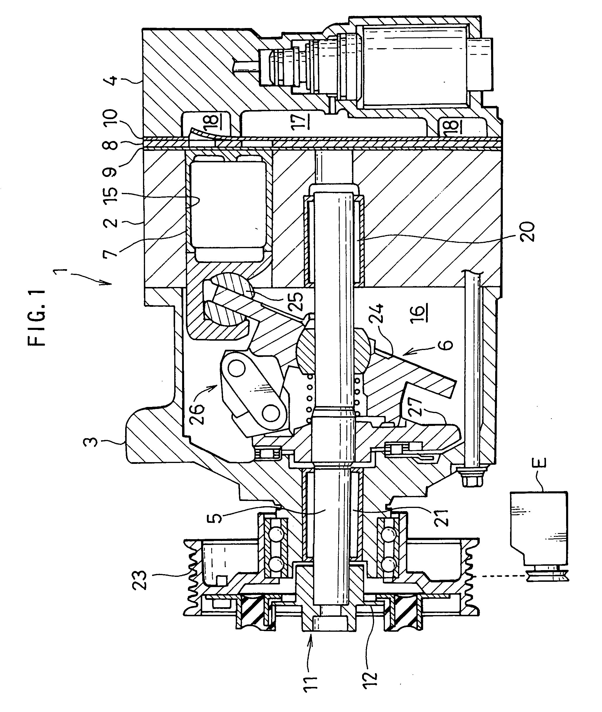
[0034] A clutchless compressor (hereafter simply referred to as a compressor) 1 in FIG. 1 comprises a cylinder block 2, a front head 3, a rear head 4, a drive shaft 5, a swashplate mechanism 6, pistons 7, a valve plate 8, an intake valve 9, a delivery valve 10, a pulley for a clutchless compressor (hereafter simply referred to as a pulley) 11 and the like. A plurality of cylinders 15 are formed at the cylinder block 2 and the pistons 7 are slidably disposed, one inside each cylinder 15. The front head 3, which seals the cylinder block 2 at one end thereof, includes a crank chamber 16 formed therein. The rear head 4, which seals the cylinder block 2 at the other end thereof, includes an intake chamber 17 and a delivery chamber 18 formed therein. The drive shaft 5 is rotatably held at bearings 20 and 21 respectively disposed at the cylinder block 2 and the front head 3, and the front end of the drive shaft 5 projects out through the front head 3. The swashplate mechanism 6, which is d...

embodiment 2

[0038] The pulley achieved in the embodiment includes a damper unit 48 adopting the structure shown in FIG. 5. In this damper unit 48, the rubber member 42 simply fills the space between the outer ring 40 and the inner ring 41, with the indented portions 44 constituting part of the engaging means formed at the inner ring 41. This structure, too, allows the time wasting manufacturing step to be eliminated when bonding the rubber member 42, thereby reducing the pulley manufacturing costs over the prior art.

embodiment 3

[0039] The pulley achieved in embodiment 3 includes a hub unit 50 adopting the structure shown in FIG. 6. The hub unit 50 includes a wall portion ranging upright from the outer edge of the disk portion 36, with projected portions 52 projecting outward formed at the wall portion 51. Advantages similar to those of embodiment 1 or embodiment 2 are also achieved by adopting the structure.


PUM


Abstract

This invention has an object to reduce the pulley manufacturing costs by eliminating a time-wasting step when bonding an elastic member of a damper unit. In a pulley for a clutchless compressor comprising a hub unit (30) fixed to a drive shaft of the compressor and a damper unit (31) disposed between a member caused to rotate in response to a drive force imparted from a drive source and the hub unit (30) to achieve a buffer effect via an elastic member (42), the hub unit (30) and the damper unit (31) are formed as separate members independent of each other and engaging means (38) and (44) used to engage the hub unit (30) and the damper unit (31) with each other are included.

Description

CROSS-REFERENCE TO RELATED APPLICATIONS [0001] This application is based upon and claims the benefit of priority from the prior Japanese Patent Application No. 2005-051503, filed on Feb. 25, 2005 the entire contents of which are incorporated herein by reference. TECHNICAL FIELD [0002] The present invention relates to a pulley mounted at a drive shaft of a clutchless compressor in an automotive air-conditioning system, and more specifically, it relates to a structure adopted in a damper assembly to achieve a buffer effect. BACKGROUND ART [0003] A clutchless compressor includes a mechanism that is linked with a drive source such as an engine at all times and adjusts the coolant compression ratio and thus, the clutchless compressor can be driven in direct response to the control executed in the air-conditioning system without having to utilize an electromagnetic clutch or the like. If a problem such as a seizure occurs at a sliding portion or a rotating portion, e.g., a piston or a bea...

Claims


Application Information

Patent Timeline
Patent Type & Authority Applications(United States)
IPC IPC(8): F16H55/36F16D3/00F16H61/00
CPCF16D3/76F16D9/06F16H55/36F16H2055/366
Inventor KOUNO, MASAYUKI
Owner VALEO SYST THERMIQUES
Why Eureka
Try Eureka