Column moving type machine tool with shield machining space

a moving type machine tool and shield technology, applied in the direction of manufacturing tools, metal-working machine components, protection and storage accessories, etc., can solve the problem of requiring a large amount of time to remove cutting chips

Inactive Publication Date: 2006-08-31
HORKOS
View PDF5 Cites 10 Cited by
  • Summary
  • Abstract
  • Description
  • Claims
  • Application Information

AI Technical Summary

Benefits of technology

[0032] According to this, the covering members for the jig support table prevent the cutting chips from splashing to the top face of the jig support tab

Problems solved by technology

In connection with this, since the lateral width of the shielded machinin

Method used


Image

  • Column moving type machine tool with shield machining space
  • Column moving type machine tool with shield machining space
  • Column moving type machine tool with shield machining space

Examples


Embodiment Construction

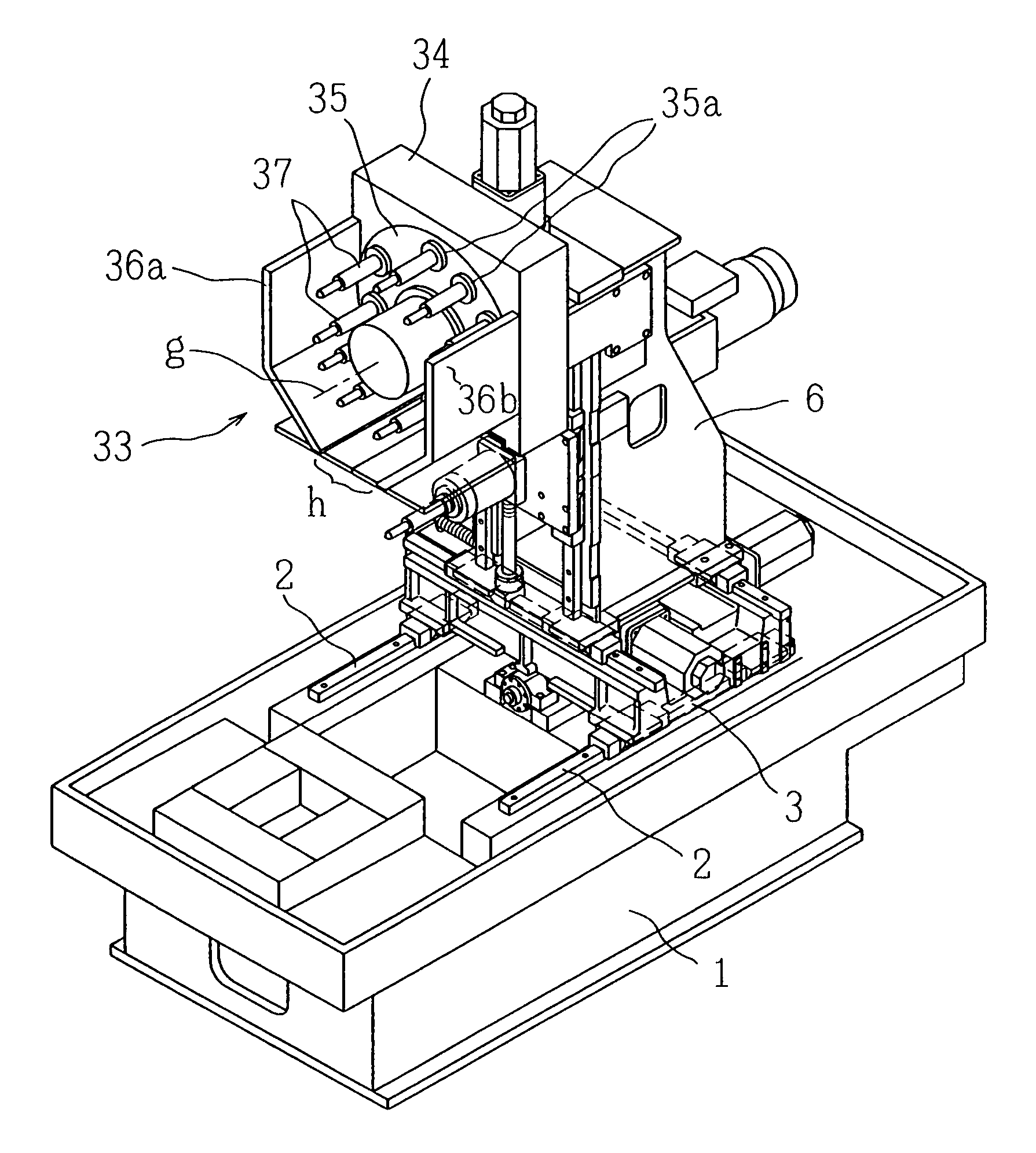
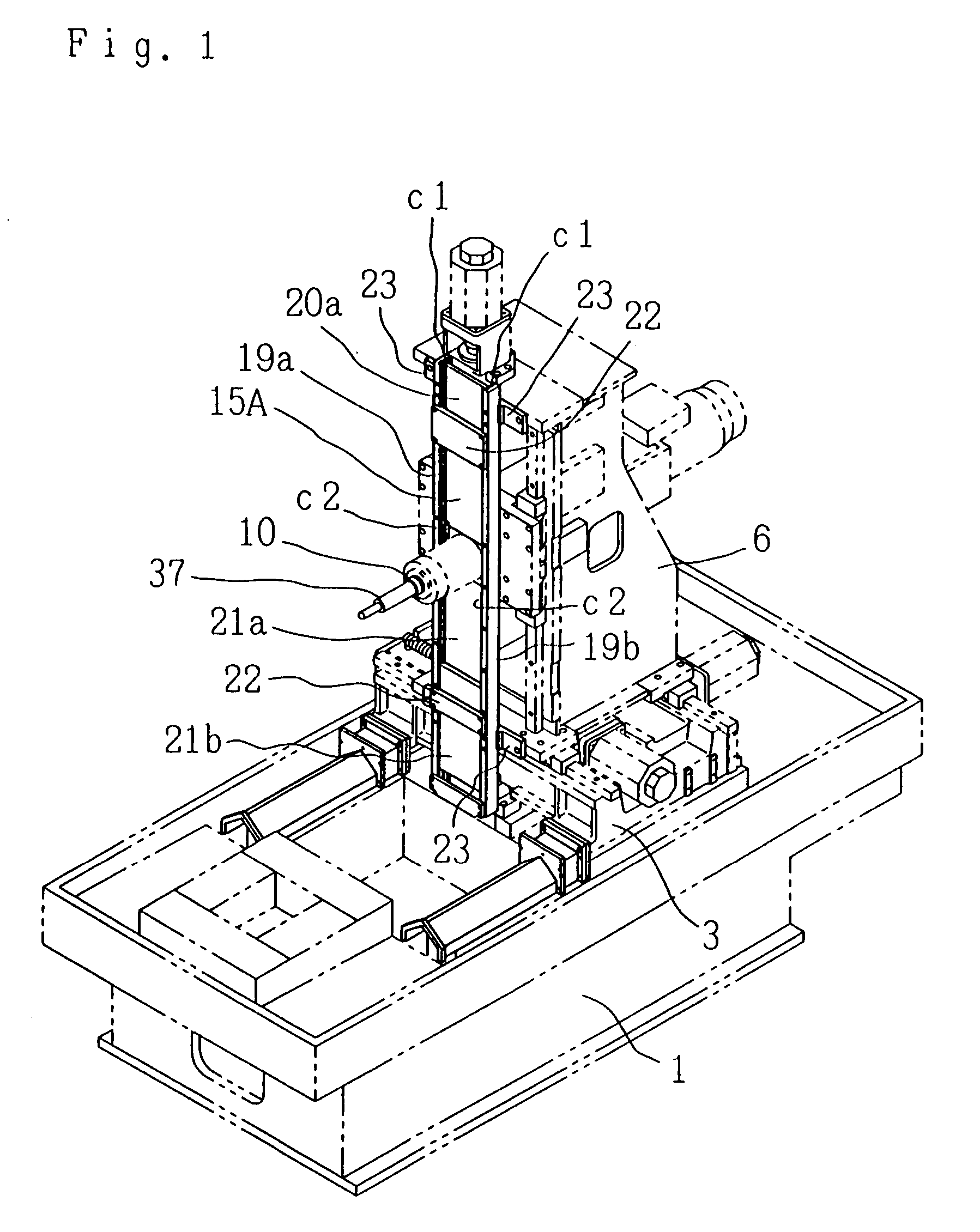
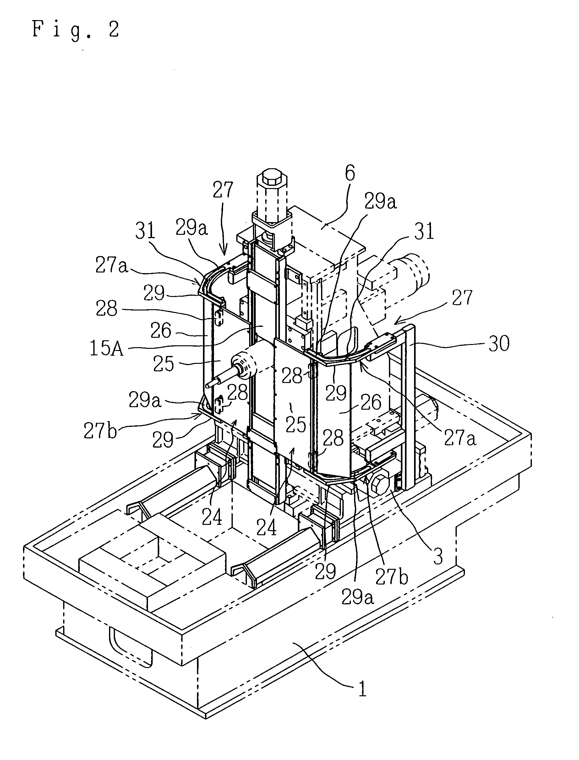
[0047] FIGS. 1 to 9 show a column moving type machining center as a machine tool related to the present invention, and in the following explanation, differences from the above-mentioned conventional example will be mainly explained.

[0048] In FIG. 1, a vertically extensible cover wall 15A, which is deformed from the conventional vertically extensible cover wall 15, is installed at the center of lateral width of a front face of a column 6.

[0049] The structure of the cover wall 15A will be explained in detail as follows. Therein, a pair of guide groove members 19a, 19b are standingly fixed to the front face of the column 6 that forms right and left sides around a bearing cylinder 11 rotatively supporting a spindle 10. An upper cover plate 20a is displaceable in a vertical direction, engaged between guide grooves c1, c1 of the guide groove members 19a, 19b above the bearing cylinder 11, and the lower end edge is combined with the upper half of the bearing cylinder 11. Two lower cover ...


PUM


Abstract

A machine tool capable of reducing the lateral width of the upper part thereof by reducing the lateral width of a bed (1) while machining through the same lateral moving distance of a spindle (10) as before, comprising longitudinal guide rails (2) installed on the bed (1), a slide (3) installed through the guide rails (2) movably in a longitudinal direction, a column (6) movable in vertical direction, wherein first cover plates (25) are fixed at the right and left sides of a vertical moving route for the spindle (10), side cover plates (26) are installed continuously with the outer end edges of the first cover plates (25) so as to be turnable rearward, a second cover plate (32) is installed at the front sides of the first cover plates (25) and the side cover plates (26) integrally with the slide (3) so as to cover the front side of the moving range of the column (6), and a shielded machining space (SK) is formed at the front of the second cover plate (32).

Description

FIELD OF THE INVENTION [0001] The present invention relates to a column moving type machine tool with a shielded machining space. BACKGROUND OF THE INVENTION [0002] There is a machining center forming a kind of column moving type machine tool as shown in FIG. 13. [0003] In the figure, 1 is a bed, a top face 1a thereof is enlarged, and a column support face 1b is formed on a part of the top face 1a. Longitudinal guide rails 2, 2 are fixed on the column support face 1b. [0004] A slide 3 is slidably and displaceably engaged with the guide rails 2, 2 to move in a longitudinal direction f1 by a motor 4. [0005] Lateral guide rails 5, 5 are fixed on the slide 3, and a column 6 is slidably and displaceably engaged with the lateral guide rails 5, 5 to move in a lateral direction f2 by a motor 7. [0006] A spindle device 8 is longitudinally installed to the column 6 to vertically move on a fixed orbit by a motor 9. [0007] In this case, the spindle device 8 comprises a longitudinal spindle 10 w...

Claims


Application Information

Patent Timeline
IPC IPC(8): B23Q3/157B23Q1/62B23Q3/155B23Q11/08B23Q39/02
CPCB23Q1/626B23Q3/15526B23Q11/08B23Q11/0891Y10T483/115Y10T483/1733Y10T409/304312Y10T483/17Y10T409/30392
Inventor SUGATA, SHINSUKESEO, YOSHINORI
Owner HORKOS
Why Eureka
Try Eureka