Apparatus and method for optimizing capacitor charge in a medical device

a capacitor and charge technology, applied in the field of stimulators for medical treatment, can solve the problems of reducing affecting the function of the battery, and affecting the life of the battery,

Active Publication Date: 2006-08-31
MEDTRONIC INC
View PDF27 Cites 30 Cited by
  • Summary
  • Abstract
  • Description
  • Claims
  • Application Information

AI Technical Summary

Benefits of technology

[0019] A medical device for electrical termination of an arrhythmic condition of a patient's heart in embodiments of the invention may include one or more of the following features: (a) at least one battery; (b) means for detection of an arrhythmic condition of a patient's heart; (c) at least one high voltage capacitor; (d) converter means for providing charging current from said at least one battery to said at least one capacitor; (e) means for maintenance of a charge on said at least one capacitor between arrhythmia therapies; (f) controller means responsive to detection of an arrhythmic condition of said patient's heart and for providing a discharge control signal; and (g) discharge circuit means for delivering voltage stored on said capacitor to said patient's heart in respo

Problems solved by technology

Either of these conditions can reach a life-threatening point at which a person suddenly loses consciousness because the heart can no longer pump enough blood to meet the body's demand.
Second, the ICD will send stronger charges to “reset” the heart if it begins ventricular fibrillation instead of beating.
However, a problem associated with rapidly charging a capacitor is that it creates a severe load on the battery.
Thus reducing the battery's life.
An additional problem associated with the high voltage capacitors of an ICD is the amount of time it takes to charge the capacitors, typically about 5 to 20 seconds.
Another problem involves providing a capacitor that maintains a high capacitance while at the same time has a reduced leakage current.
Therefore, the constant recharging and the length between the recharging of the capacitors actually increases the amount of leakage current.
A high leakage current can resul

Method used


Image

  • Apparatus and method for optimizing capacitor charge in a medical device
  • Apparatus and method for optimizing capacitor charge in a medical device
  • Apparatus and method for optimizing capacitor charge in a medical device

Examples


Embodiment Construction

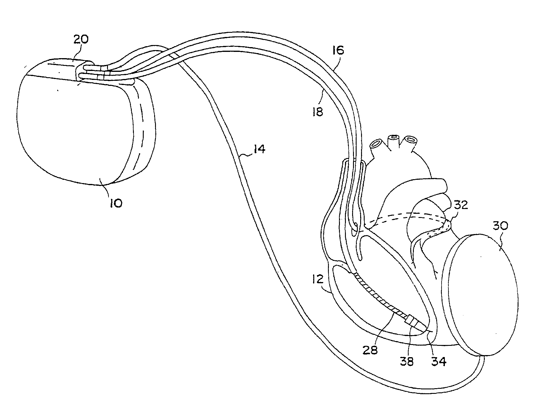
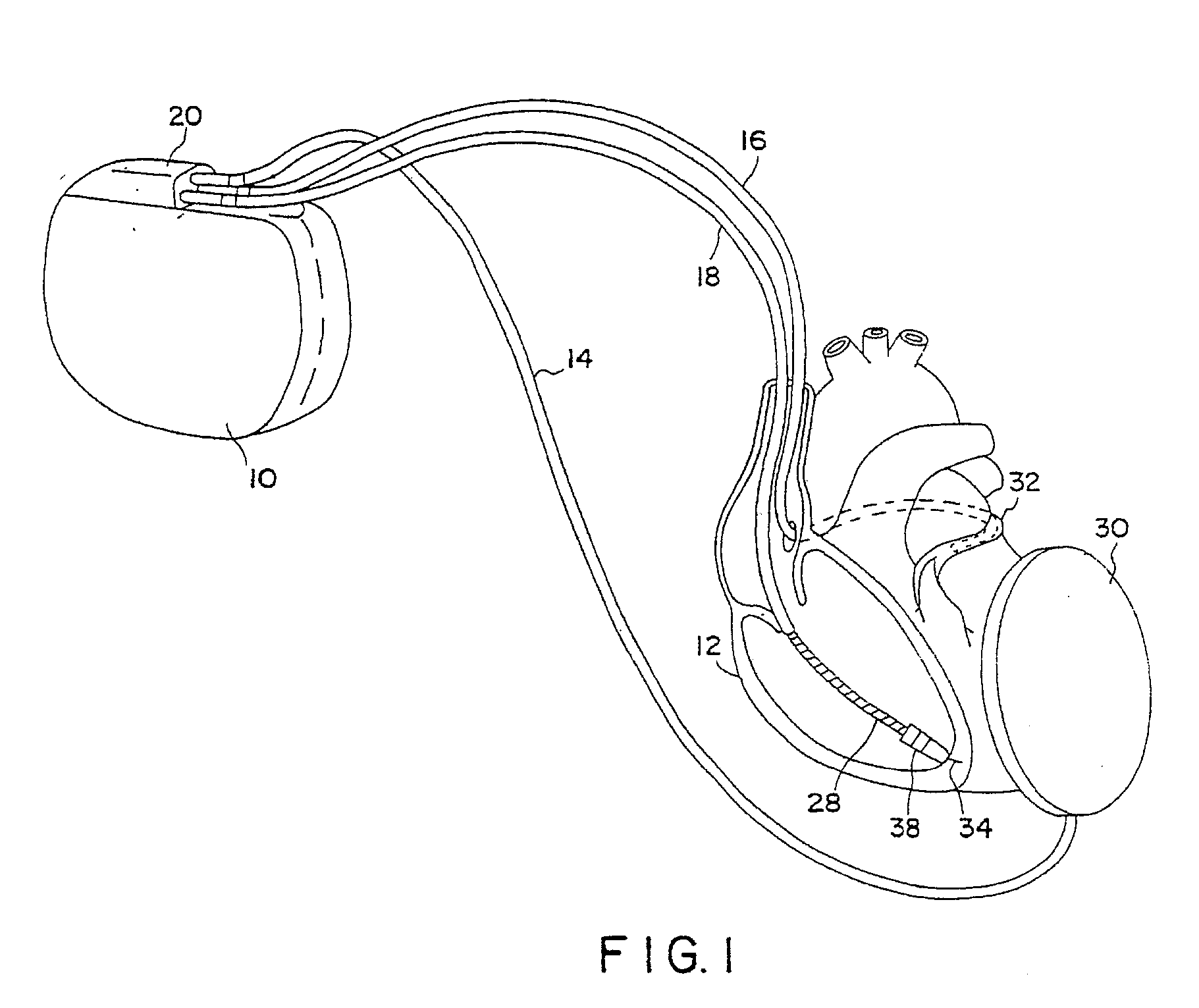
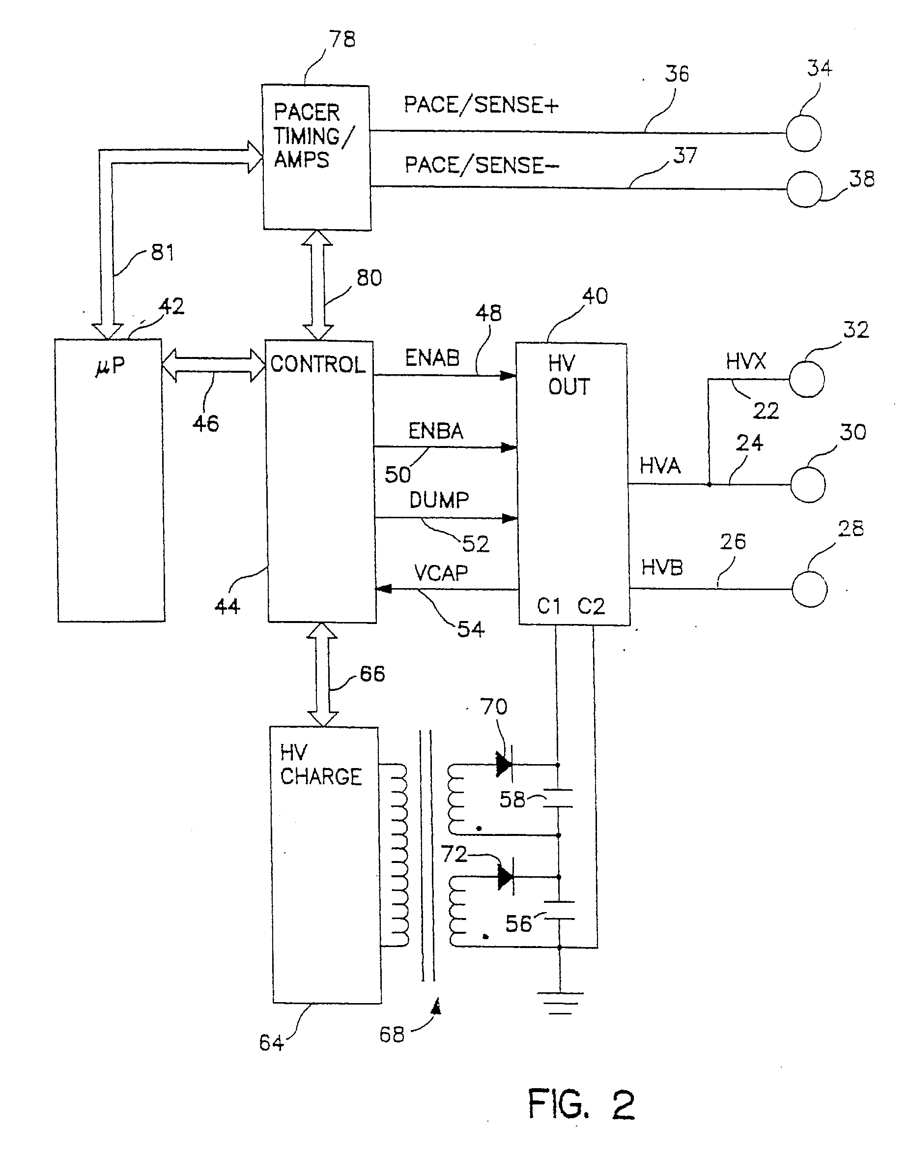
[0027] The following detailed description is to be read with reference to the figures, in which like elements in different figures have like reference numerals. The figures, which are not necessarily to scale, depict selected embodiments and are not intended to limit the scope of the invention. Skilled artisans will recognize that the examples provided herein have many useful alternatives that fall within the scope of the invention.

[0028] The present invention is not limited to implantable cardioverter defibrillators and may be employed in many various types of electronic and mechanical devices for treating patient medical conditions such as external cardioverter defibrillators, pacemakers, and neurostimulators. It is to be further understood; moreover, the present invention is not limited to medium current rate batteries and may be utilized for low and high current rate batteries. For purposes of illustration only, however, the present invention is below described in the context o...


PUM


Abstract

A medical device for electrical termination of an arrhythmic condition of a patient's heart in embodiments of the invention may include one or more of the following features: (a) at least one battery; (b) means for detection of an arrhythmic condition of a patient's heart; (c) at least one high voltage capacitor; (d) converter means for providing charging current from said battery to said capacitor; (e) means for maintenance of a charge on said capacitor between arrhythmia therapies; (f) controller means responsive to detection of an arrhythmic condition of said patient's heart and for providing a discharge control signal; and (g) discharge circuit means for delivering voltage stored on said capacitor to said patient's heart in response to said discharge control signal.

Description

CROSS-REFERENCE TO RELATED APPLICATIONS [0001] This application is a continuation-in-part of U.S. patent application Ser. No. 10 / 260,488 entitled “APPARATUS AND METHOD FOR OPTIMIZING CAPACITOR CHARGE IN A MEDICAL DEVICE”, filed Sep. 30, 2002.FIELD OF THE INVENTION [0002] The present invention relates generally to stimulators for medical treatment by means of voltage shocks, and more particularly to cardioverters and defibrillators and electrode systems for use in conjunction therewith. BACKGROUND OF THE INVENTION [0003] A defibrillator can be used to restore a normal heart rhythm by delivering an electrical shock to the heart when the heartbeat is dangerously fast due to ventricular tachycardia or ventricular fibrillation. Either of these conditions can reach a life-threatening point at which a person suddenly loses consciousness because the heart can no longer pump enough blood to meet the body's demand. For patients suffering from chronic arrhythmias involving ventricular tachycar...

Claims


Application Information

Patent Timeline
IPC IPC(8): A61N1/39
CPCA61N1/3975A61N1/3981
Inventor NORTON, JOHN D.RORVICK, ANTHONY W.
Owner MEDTRONIC INC
Why Eureka
Try Eureka