
Model Car Racing Simulator

a simulator and model car technology, applied in the field of amusement devices, can solve the problems of limiting the number of active users, preventing the user of the system from interactively controlling pit stop functions, and unable to realistically control the vehicl

Inactive Publication Date: 2006-09-07
FAULCON RENE GERARD
View PDF22 Cites 18 Cited by
  • Summary
  • Abstract
  • Description
  • Claims
  • Application Information

AI Technical Summary

Problems solved by technology

However, that invention severely limits the number of active users and precludes the user of the system to interactively control pit stop functions.
Nor does that system allow realistic vehicle control functions such controlling vehicle lights, brakes, and actually steering into or out of a desired lane or pit stop location.
In addition the system only allows for a single vehicle per lane which forces entry to the pits from an outside lane by at least one toy vehicle which is unrealistic from the standpoint of a realistic race simulation.
While that invention improves on the interactivity between the user and the toy, it too only allows a single vehicle per lane, thus forcing vehicles to “pit” in two lanes which, too is unrealistic from a racing simulation point of view.
While the pit function indicates some sort of attention is needed, it does not allow the operator to either bypass or partially address a particular problem and accept the consequences of his actions in the interest of saving time.
Lap counting and timing by design are limited to 100 laps and 1 / 100th of a second which is not suitable for realistic racing simulation.
In addition, no realistic means for lap counting or timing is there identified.
This often has a negative impact on available space and the available designs of the resulting race course.
While innovative, this art continues to restrict the racing simulation to only two toy vehicles and includes no other unique, interactive functionality.
While it is best to match controller performance to vehicle performance, controllers available today are difficult or time-consuming to customize.
Thus some purchase multiple, pre-configured controllers or endure an unsatisfying experience attempting to control a slot car for which their controller is not suitably matched.

Method used


Image

  • Model Car Racing Simulator
  • Model Car Racing Simulator
  • Model Car Racing Simulator

Examples


Embodiment Construction

is to follow and shall include numerals to represent common, significant components appearing in the above referenced figures.

DETAILED DESCRIPTION OF THE DRAWING

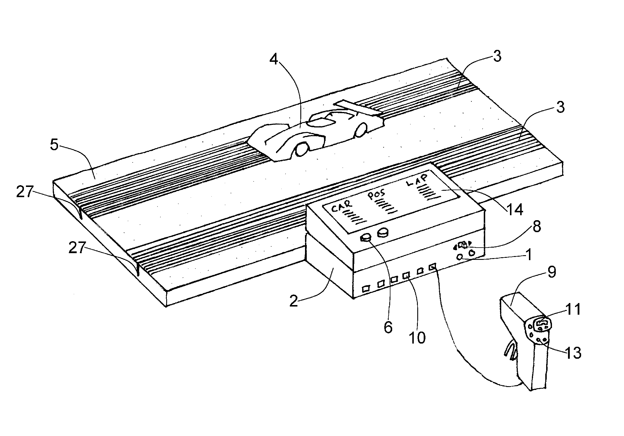
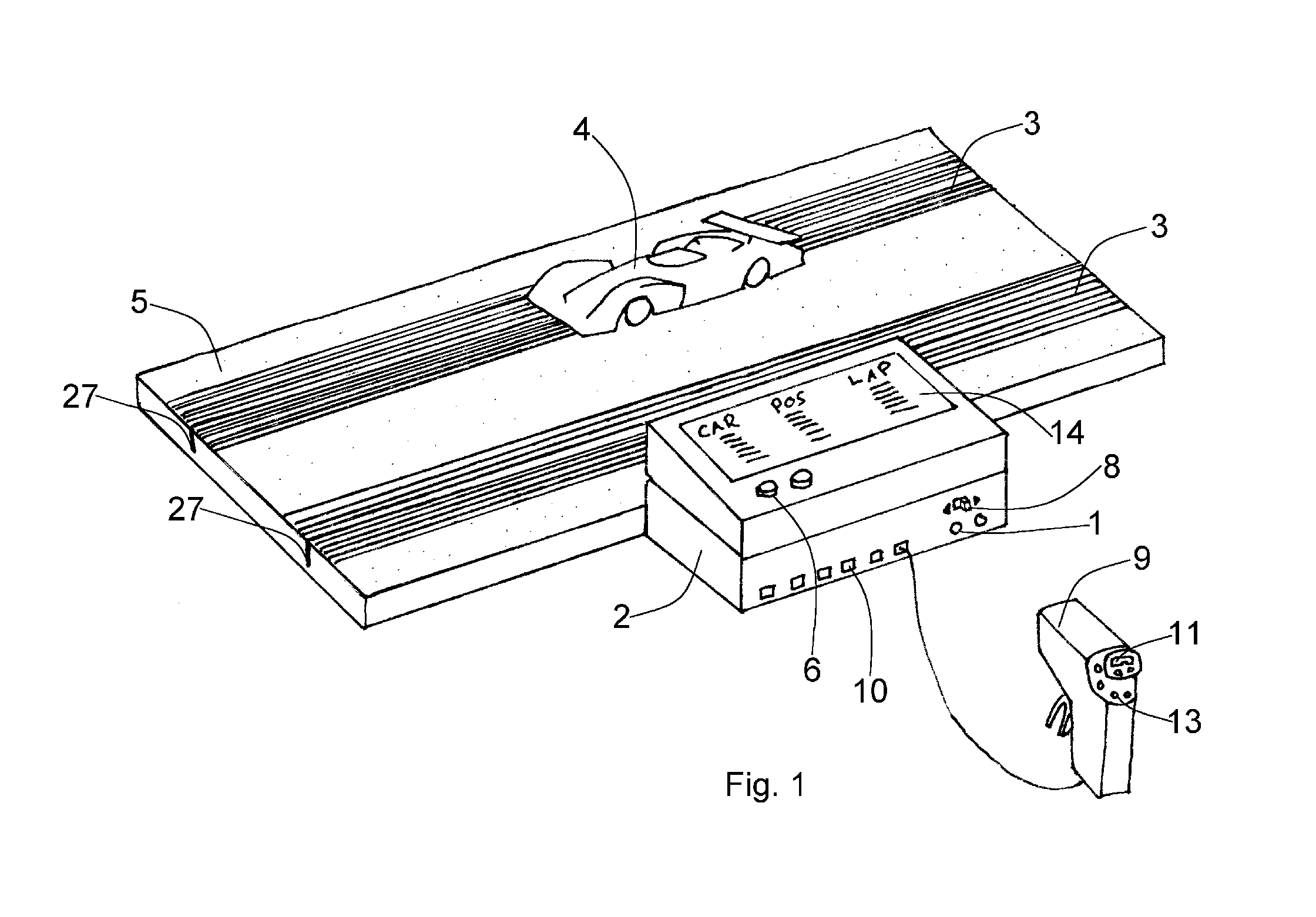
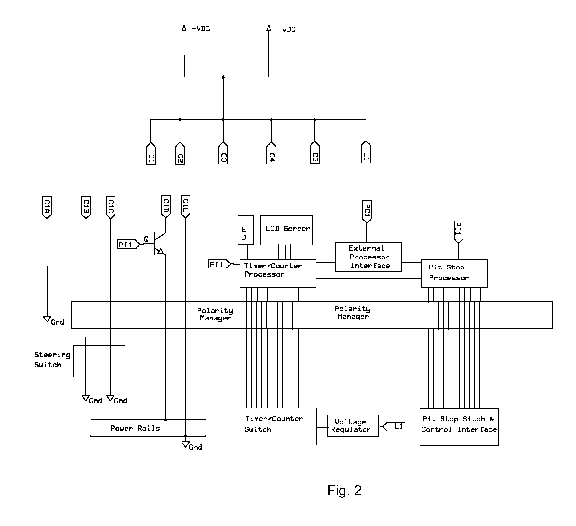
[0031] A base unit 2 as appearing in FIG. 1 connects to at least one track segment 5 which uses a plurality of electrically conductive rails 3 and a slot 27 for the guide flag of an electrically powered toy vehicle 4. The control unit allows vehicle travel and lap counting for vehicles traveling either in clockwise or counter-clockwise direction via a switch 8 mechanism. The base unit 2 supports a plurality of vehicles 4 and thus hand held control units 9 via connections 10 for hand held control units 9 or other accessories which may include lighting and otherwise. The base unit 2 is comprised of simple electrical components, allowing connection of analog hand controllers for select third parties. The base unit 2 also supports multiple DC power supply devices via power ports 1. The track segments include an electrical and m...


PUM


Abstract

A model car racing simulator game which employs a unique, configurable guide blade and rails system which consist of a plurality of brush connections and rails to create a unique path for power and control data to individual toy vehicles so that they may change lanes and race in the same lane to more realistically emulate actual automotive racing. Modular power base units are described herein allowing a larger field of vehicles to race simultaneously. Such a field of vehicles ranges in size from 1 to 25 or more vehicles within this description and may include more depending upon rail and guide configuration implemented. The invention includes track segments as well as processing and display means which allow for lane changes, lap counting and timing, pit stops. The invention includes a control device which allows control of a subset of features including though not limited to vehicle steering, vehicle speed, braking, lights, brake lights.

Description

FIELD OF INVENTION [0001] The present invention is related to amusement devices generally depicting simulation of vehicle travel or racing. In particular this invention relates to vehicles which are electrically powered and guided by a slot or groove in a simulated raceway or path. BACKGROUND OF INVENTION [0002] The invention pertains to the activity or hobby of slot car or model car racing. For nearly 40 years this activity has utilized rubber or plastic roadway or track which is fitted with two electrical rails for each given lane. The electrical power, typically direct current (DC), passes through a means of varying voltage to the track and thus the electric motor inside the toy vehicle which would vary its speed on the track. [0003] The challenge aspect of the hobby was increased by an introduction of modular track pieces to vary track layouts. In addition timing and lap counting were added and are generally accepted as common within the art. To improve the aspects of challenge ...

Claims


Application Information

Patent Timeline
IPC IPC(8): A63G7/00
CPCA63H18/005A63H18/026A63H18/08A63H18/12
Inventor FAULCON, RENE GERARD
Owner FAULCON RENE GERARD
Learn More