Vacuum breaker

a vacuum breaker and breaker technology, applied in mechanical equipment, transportation and packaging, valve types, etc., can solve problems such as inaccuracy of response and control

Inactive Publication Date: 2006-09-07
FLUSHTECH CORP
View PDF9 Cites 28 Cited by
  • Summary
  • Abstract
  • Description
  • Claims
  • Application Information

AI Technical Summary

Benefits of technology

[0005] The primary object of the present invention is to provide a vacuum breaker which has a rigid mechanism to actuate opening and closing of flushing to overcome the disadvantages occurred to the conventional vacuum breakers that cannot flush normally due to material fatigue.

Problems solved by technology

However, when fatigues or damage occurs to the material after used for a period of time, response and control become not accurate, and sewage could counter flow through the not closely sealed bushing and contaminate drinking water.

Method used


Image

  • Vacuum breaker
  • Vacuum breaker
  • Vacuum breaker

Examples


Embodiment Construction

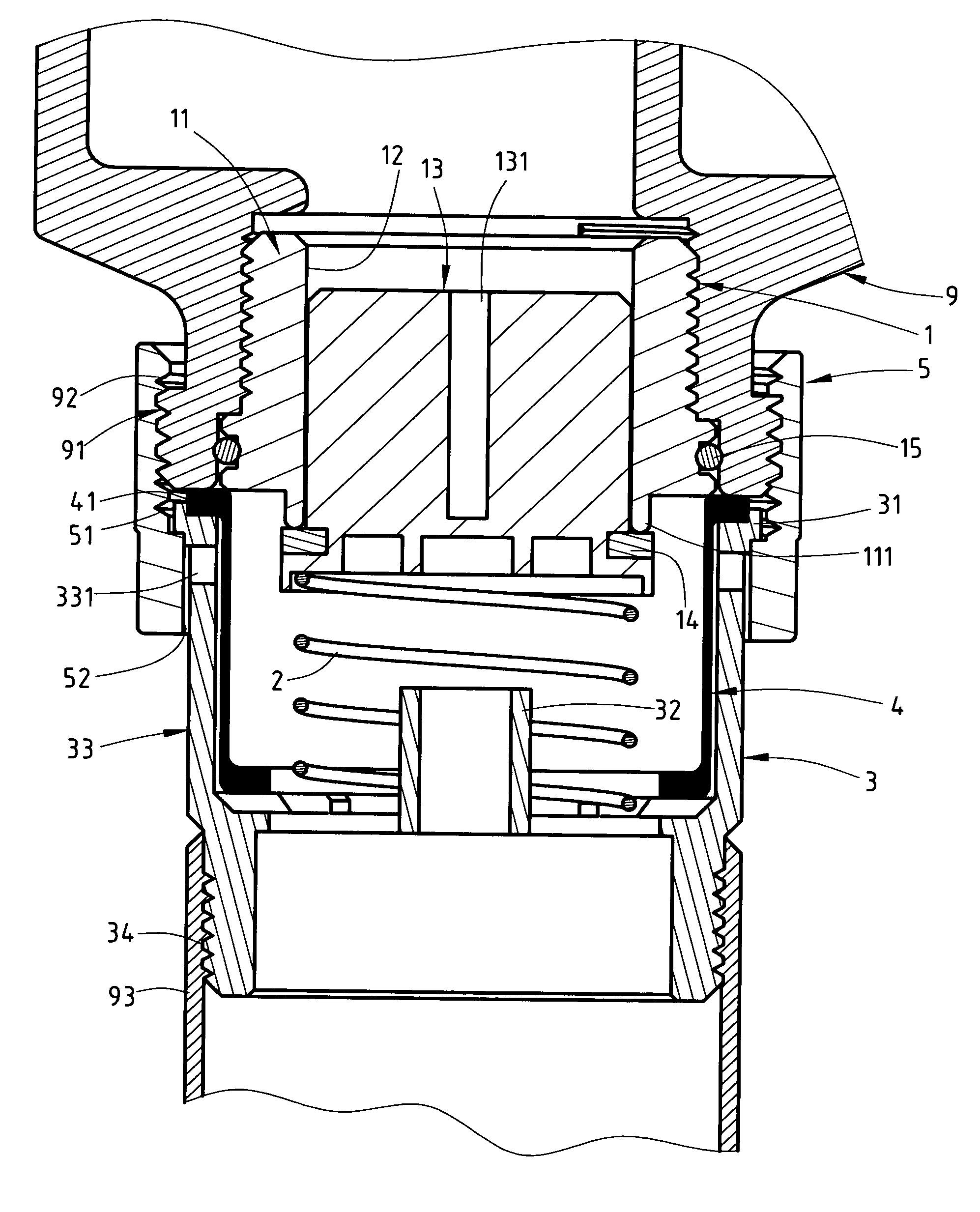
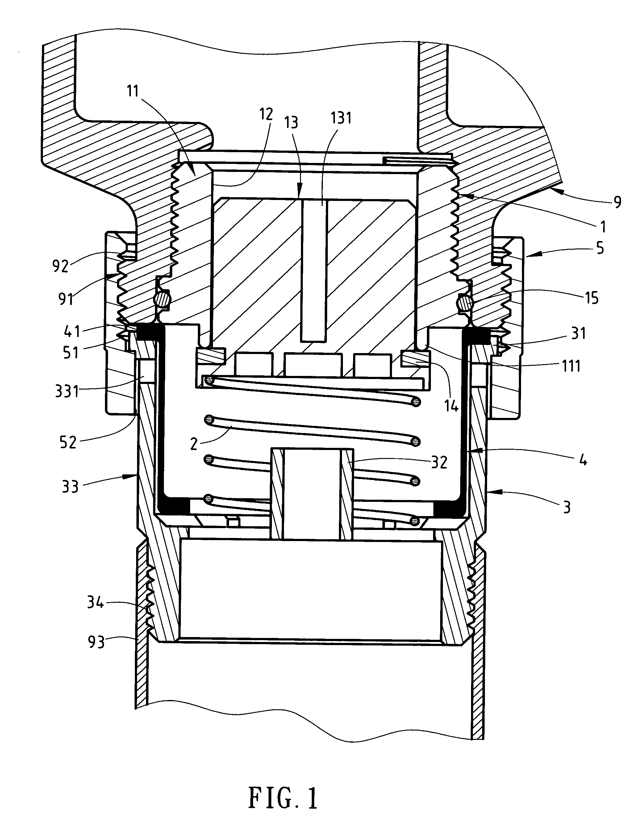
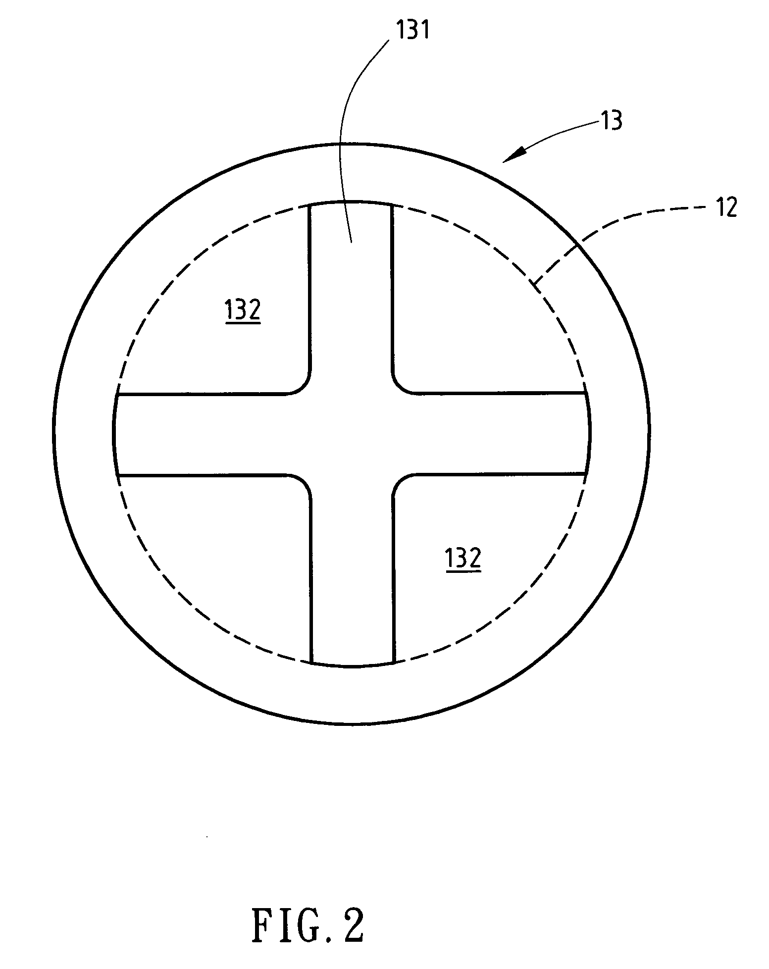
[0015] Refer to FIGS. 1 and 2 for an embodiment of the vacuum breaker of the invention. It is installed on a water discharge end 91 of a flush valve 9. It includes a valve 1, a spring 2, a coupling duct 3, a bushing 4 and a nut 5. The valve 1 has a valve seat 11 screwing in the water discharge end 91 of the flush valve 9. The bottom of the valve seat is coupled with an O-ring 15. The valve seat 11 has a hollow section 12 to house a plug 13 which is movable up and down. The plug 13 has a bottom coupled with a retaining ring 14 which seals a bottom end 111 of the valve seat 11 when flushing is stopped. The plug 13, referring to FIG. 2, has a cross rib 131 on a upper side forming a plurality of water inlets 132 corresponding to the hollow section 12 of the valve seat 11 so that water flushing from the flush valve 9 passes through the plug and is divided into several water streams to become a more stable water flow. The spring 2 has one end pressing the bottom of the plug 13 and other e...


PUM


Abstract

A vacuum breaker is adopted for use on a water discharge end of a flush valve in a water supply piping system. It includes a valve which has a valve seat with a hollow section to house a plug. The plug is movable up and down under water pressure and a spring on the bottom to actuate flushing or stop flushing. The vacuum breaker further includes a coupling duct and a bushing housed in the coupling duct that is made from a flexible material. The coupling duct has a plurality of apertures near the top end. The outer wall of the bushing and the inner wall of the coupling duct form a gap therebetween. During flushing, the wall of the bushing is expanded outwards under water pressure to close the apertures to stop water overflow through the apertures. When the flushing stops, external air can enter through the apertures and the gap between the coupling duct and the bushing to balance the internal and external pressure and eliminate vacuum, and prevent back siphonage from occurring.

Description

BACKGROUND OF THE INVENTION [0001] 1. Field of the Invention [0002] The invention relates to a vacuum breaker installed on a water discharge water end of a flush valve of toilet devices to eliminate vacuum in the flush valve through a plug which may return automatically and a flexible and deformable bushing and prevent sewage from counter flowing and contaminating clean water. [0003] 2. Description of the Prior Art [0004] Vacuum breaker is installed in a discharge tube of a flush valve to prevent back siphonage from occurring to the toilet or urinal that would result in counter flow to contaminate clean water. Conventional vacuum breakers such as those disclosed in U.S. Pat. Nos. 3,334,646 and 5,564,460 mainly have a flexible bushing with a discharge end temporarily open under the pressure of flushing water and closed after the flushing finishes. Moreover, the bushing wall will be expanded outwards during flushing to close air outlets of the water discharge tube to prevent water fro...

Claims


Application Information

Patent Timeline
Patent Type & Authority Applications(United States)
IPC IPC(8): E03C1/10
CPCF16K15/026F16K24/02E03C1/104E03C1/108E03D3/02Y10T137/3331
Inventor YEN, CHIH-CHEN
Owner FLUSHTECH CORP
Why Eureka
Try Eureka