
Heater and heating device with heaters

a heating device and heater technology, applied in the direction of transit-tube circuit elements, structural circuit elements, cathode-ray/electron beam tube circuit elements, etc., can solve the problems of inferior goods, crystal transition defect, and disadvantage described below in the above described conventional heating device, so as to reduce the size of the device and reduce the uniformity of temperature distribution

Inactive Publication Date: 2006-09-07
USHIO DENKI KK
View PDF5 Cites 66 Cited by
  • Summary
  • Abstract
  • Description
  • Claims
  • Application Information

AI Technical Summary

Benefits of technology

[0022] The invention was devised to eliminate the above described disadvantages in the prior art. Thus, a primary object of the invention is to devise a heating device in which uniform heating of a substrate is possible even in the case of a distribution of the degree of local temperature change on the substrate which is to be thermally processed is asymmetrical with respect to the shape of the substrate, in which uniform heating of the article to be processed is also possible in the case of formation of a temperature change which leads to a loss of the uniformity of the temperature distribution in a narrowly delineated area, and in which a reduction in the size of the device is possible.
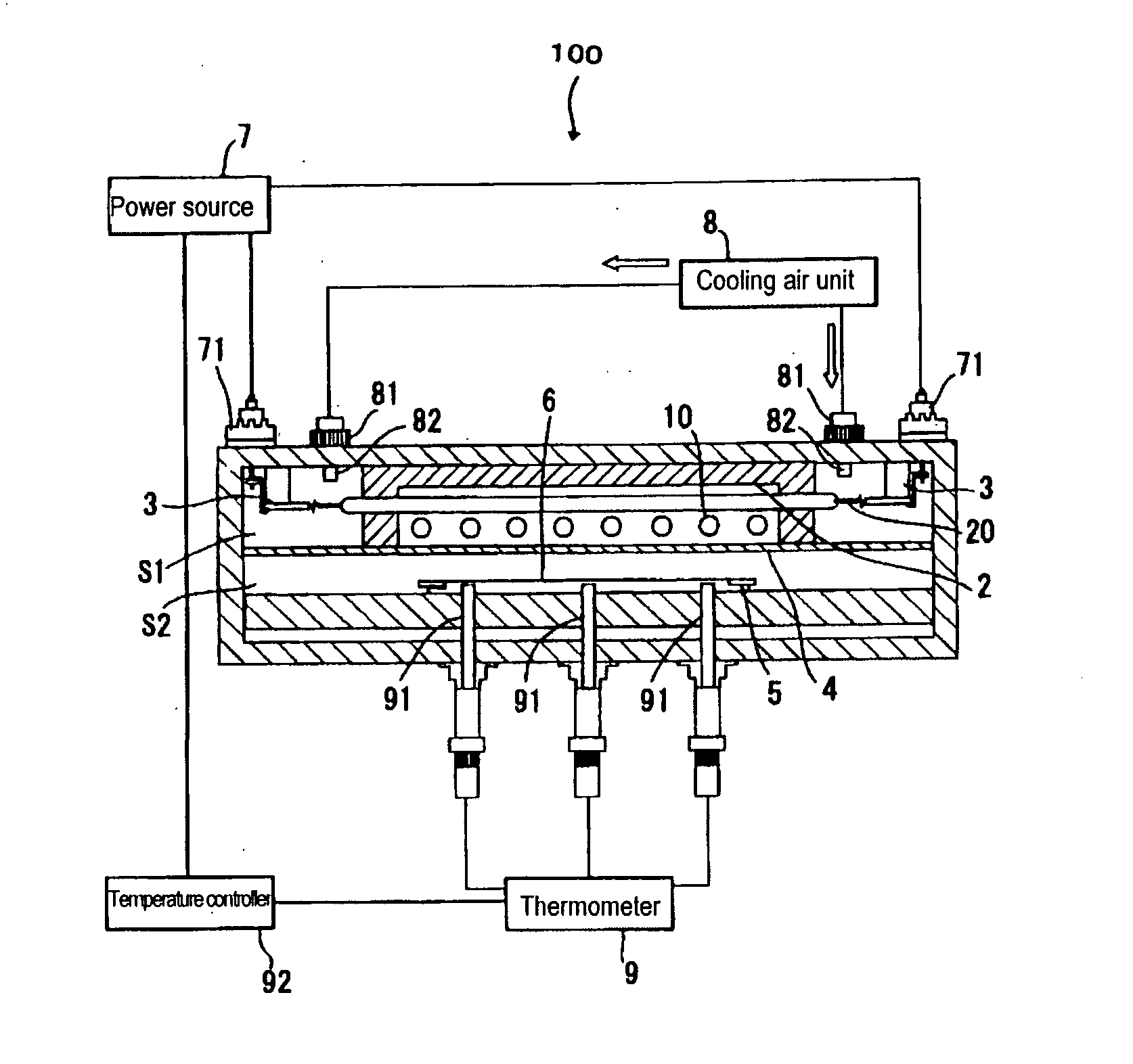
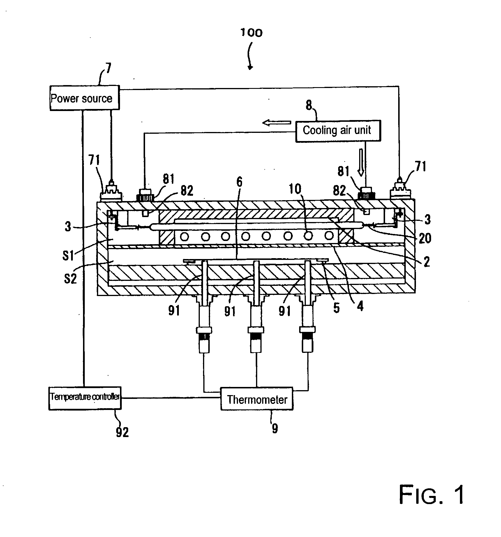
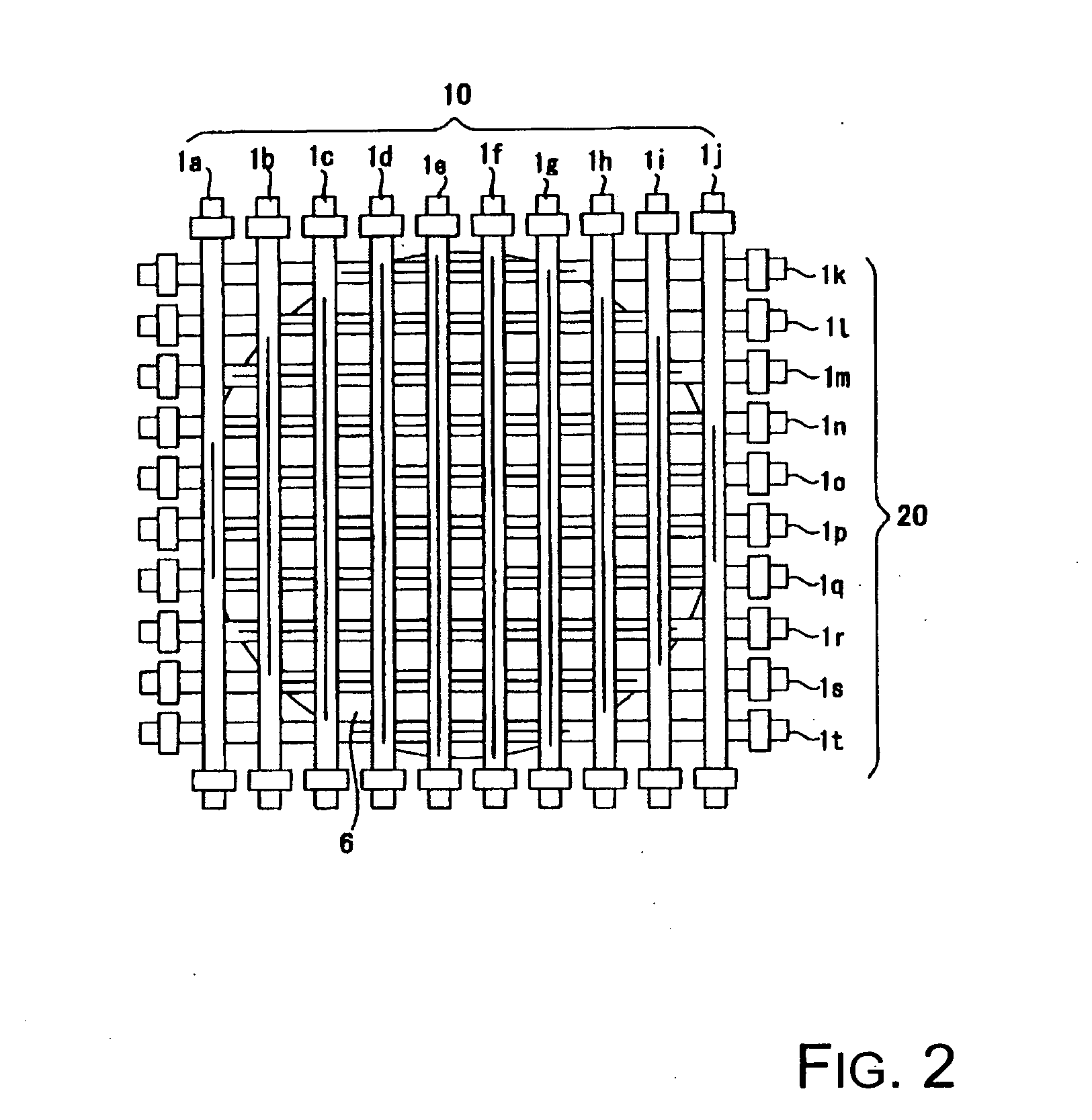
[0038] The distance between the individual filaments can be made extremely small without a space with a rather large total length which does not contribute to emission being present between the individual filaments due to the presence of two silica glass walls or for similar reasons, as is the case in the conventional device, by a heating device with a lamp unit composed of an array of a plurality of heaters, in which within a single bulb there are several heater filaments formed by division arranged along the axis of the bulb in the axial direction of the bulb. Therefore, the temperature distribution of the article to be processed can be made more uniform than in a conventional device. Moreover, the size of the heating device can be reduced by the space (mainly in the vertical direction) which is necessary for the arrangement of the heaters being made smaller.
[0039] Furthermore, the above described heating device with a lamp unit enables adjustment of the distribution of the illuminance on the article to be processed which has been moved away from the lamp unit by a given distance in a precise manner, and moreover, in any distribution. Adjustment of the distribution of illuminance on the article to be processed which is asymmetrical to the shape of the article to be processed is therefore enabled. In the case in which the distribution of the degree of local temperature variation on the substrate which constitutes the article to be processed and which is being thermally processed is asymmetrical to the shape of the substrate, a corresponding adjustment of the distribution of the illuminance on the article to be processed is enabled, by which uniform heating of the article to be processed is possible.

Problems solved by technology

When the article to be processed is, for example, a semiconductor wafer, and if no uniformity of the temperature distribution is caused in the semiconductor wafer during heating, there is the possibility that a defect of crystal transition occurs, that is, a phenomenon called slip in the semiconductor wafer, and inferior goods will be formed.
However, it was found that the disadvantage described below arises in the above described conventional heating device.
This means that the temperature cannot be controlled in a narrow area, resulting in the following disadvantages:
the functions which are desired for the article to be processed are adversely affected by it.
However, only the horizontal part in which the filament is located contributes to emission.
As a result, it can be imagined that the disadvantage arises that a nonuniformity of temperature occurs in the area directly underneath this space.
Therefore, it can be imagined that it is relatively difficult to reduce the temperature nonuniformity in the vicinity of the area directly underneath the above described space even if heating which corresponds to the temperature change of the respective zone is to be carried out.
Also, since, in such a thermal processing device, there has recently been the tendency to make the space (mainly in the vertical direction) for the arrangement of the lamp units extremely small, when using U-shaped lamps, a space is required which corresponds to the vertical part of the lamp.
This thermal processing device is therefore not advantageous with respect to the saving of space in the vertical direction.

Method used


Image

  • Heater and heating device with heaters
  • Heater and heating device with heaters
  • Heater and heating device with heaters

Examples


first embodiment

[0087] the heater of the invention is described below with reference to FIGS. 7(a) &7(b). As is shown in FIGS. 7(a) &7(b), the heater 1 is made of a transparent material, such as, for example, silica glass or the like. It has a bulb 11 with a cross section which has an elliptical shape in a plane which orthogonally intersects its axial direction. “Elliptical shape” means all shapes (for example, an oval shape and the like) in which the length a of the major diameter in the longitudinal direction of the above described cross section is larger than the length b of the minor diameter in the direction perpendicular to the longitudinal direction of the above described cross section. The above described cross section can also be circular in the bulb 11.

[0088] For the bulb 11, on one of the ends, metal foils 13a, 13b, are installed and a hermetically sealed portion 12a is formed by a pinch seal. On the other end of the bulb 11 metal foils 13c, 13d are installed and a hermetically sealed po...

second embodiment

[0115] the heater of the invention is described below with reference to FIG. 8. In FIG. 8, the parts corresponding to the same parts as in FIGS. 7(a) &7(b) are provided with the same reference numbers as in FIG. 7(a) and (b).

[0116] As is shown in FIG. 8, for a heater 40 according to the second embodiment, there are two filament parts 14a, 14b which are arranged coaxially along the axis of bulb 11. Between the filament part 14a and the filament part 14b, an insulator 41, for example, made of silica glass, is arranged such that there is a space between the filament part 14a and the filament part 14b. Furthermore, the insulator 41 can border the filament parts 14a, 14b. The lead wire 15d passes through a through opening 42 which is provided in the insulator 41. For the lead wire 15d, the outside of the area which is opposite the filament part 14b is covered with an insulating tube 16b. One end of the lead wire 15d is electrically connected to a metal foil 13d, while the other end is el...

third embodiment

[0120] the heater in accordance with the invention is described below with reference to FIG. 9. In FIG. 9, the parts corresponding to the same parts as in FIGS. 7(a) &7(b) are provided with the same reference numbers as in FIGS. 7(a) &7(b).

[0121] As is shown in FIG. 9, for a heater 50, there are two filament assemblies 51, 52 located opposite each other in the bulb 11, separated by an insulator 53. The two filament parts 14a, 14b are arranged coaxially along the axis of the bulb 11. The insulator 53 is arranged such that there is a space between the filament part 14a and the filament part 14b. It is advantageous for the distance G4 between the filament part 14a and the filament part 14b to be in the range from 3 mm to 8 mm, so that the variation of the intensity distribution of the light which has been emitted onto the article to be processed can be reduced to an extreme degree and no unwanted discharge occurs between the filament parts 14a &14b, which lie in succession in the longi...


PUM


Abstract

A heating device in which uniform heating of an article to be processed is possible even in the case a temperature change which leads to a loss of the uniformity of the temperature distribution in a narrowly delineated area, and in which a reduction in the size of the device is possible. The heating device has a plurality of heaters, each heater having a single bulb of transparent material in which there is a filament that is divided in the axial direction into several filament parts and the respective filament parts are supplied with power independently of each other.

Description

BACKGROUND OF THE INVENTION [0001] 1. Field of the Invention [0002] The invention relates to a heater and a heating device with heaters. The invention relates especially to a heater and a heating device with heaters for irradiating an article to be processed with light which is emitted for purposes of heating of the object to be processed. [0003] 2. Description of Related Art [0004] In general, thermal processing is used in the production of semiconductors in different processes, such as layer formation, oxidation diffusion, diffusion of impurities, nitriding, layer stabilization, silicide generation, crystallization, ion implantation-activation and the like. To improve the yield and the quality in the production of semiconductors, rapid thermal processing (RTP) is desired, in which the temperature of an article to be processed, such as a semiconductor wafer or the like, is rapidly raised or lowered. In RTP, a thermal processing device of the light irradiation type using light irrad...

Claims


Application Information

Patent Timeline
IPC IPC(8): H01J13/46
CPCH01K7/00H01K9/08H01L21/67115H05B3/0033H05B2203/032H01L21/26
Inventor MIZUKAWA, YOICHIKANAZU, KEITAYOSHIOKA, MASAKISUZUKI, SHINJISEKI, KYOHEI
Owner USHIO DENKI KK
Learn More