Method for starting single phase BLDCM having asymmetrical air gap

a single-phase bldcm and air gap technology, which is applied in the direction of motor/generator/converter stopper, pulse technique, dynamo-electric converter control, etc., can solve the problems of increasing the size of the motor system and manufacturing costs, reducing the ability of the system to resist the environment variation, and difficult to star

Inactive Publication Date: 2006-09-07
DELTA ELECTRONICS INC
View PDF15 Cites 21 Cited by
  • Summary
  • Abstract
  • Description
  • Claims
  • Application Information

AI Technical Summary

Benefits of technology

[0006] It is therefore an object of the present invention to propose a method for starting a single phase BLDCM having an asymm

Problems solved by technology

However, the Hall sensor itself increases the size of the motor system and the manufacturing costs.
Besides, the Hall sensor decreases the capability of the system against the environment variation, e.g., the temperature variation.
The single phase motors have null-points in their torque waveforms, which make them difficult

Method used


Image

  • Method for starting single phase BLDCM having asymmetrical air gap
  • Method for starting single phase BLDCM having asymmetrical air gap
  • Method for starting single phase BLDCM having asymmetrical air gap

Examples


Embodiment Construction

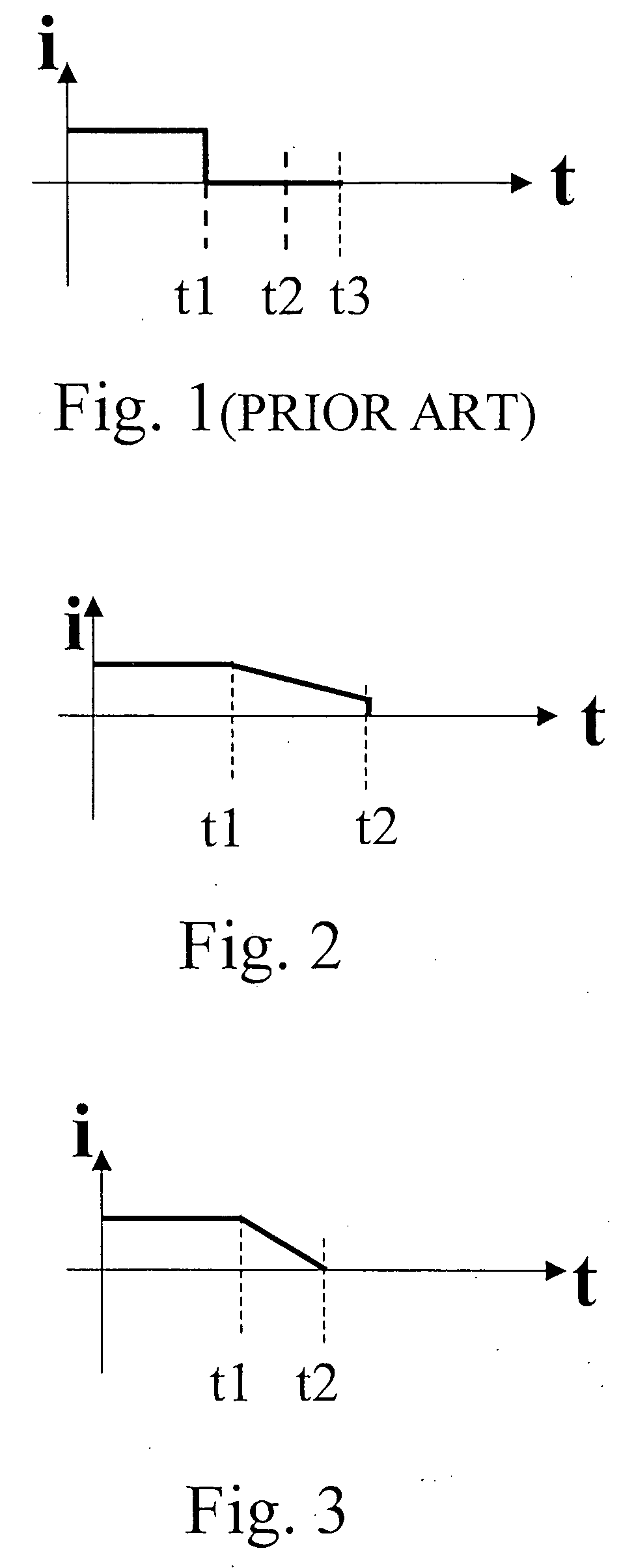
[0036] Please refer to FIGS. 1 and 3. FIG. 1 is the graph of current versus time illustrating the current impulse for positioning the rotor of a single phase permanent magnet motor disclosed in the prior art of the '419 Patent and FIG. 3 is the graph of current versus time illustrating the current impulse for positioning the rotor of a Hall-less single phase BLDCM having an asymmetrical air gap, in which the current impulse value at time t2 is equal to zero ampere and the rotor is positioned at a specific position at time t2, respectively. The method of starting a single phase permanent magnet motor disclosed in the '419 Patent has the drawbacks of failing to position the rotor due to the oscillation of the rotor. On the contrary, the method proposed in the present invention could avoid the drawbacks of the '419 Patent and has relatively better effects for positioning the rotor of the single phase BLDCM having an asymmetrical air gap.

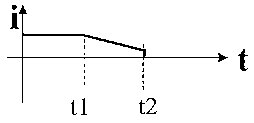
[0037] Please refer to FIG. 2. FIG. 2 is the gra...


PUM


Abstract

The proposed method for starting a motor having a stator, a rotor, a winding and an asymmetrical air gap, comprising the steps of: (a) exciting said winding with a current impulse such that said stator generates a magnetic field and going to one of steps (b) and (d); (b) driving said rotor to rotate in a first direction if a polarity of a portion of a specific tooth of said stator close to said air-gap and a polarity of a specific magnetic pole of said rotor corresponding to said tooth are opposite; (c) stopping said current impulse at a specific moment such that said rotor is rotated in a second direction by a cogging torque and going to step (f); (d) driving said rotor to rotate in a first direction if a polarity of a portion of a specific tooth of said stator close to said air-gap and a polarity of a specific magnetic pole of said rotor corresponding to said tooth are the same; (e) stopping said current impulse at said moment such that said rotor is rotated in a second direction by an inertia; and (f) detecting a back electromotive force (BEMF) in said winding when said rotor is rotated such that said motor is controlled for commutating according to said BEMF. The provided method overcomes the drawbacks of failing to position the rotor due to the oscillation of the rotor in the prior art.

Description

FIELD OF THE INVENTION [0001] The present invention relates in general to the control of a single phase brushless DC motor (BLDCM). More particularly, the present invention relates to the starting method for a Hall-less single phase BLDCM having an asymmetrical air gap. BACKGROUND OF THE INVENTION [0002] The single phase BLDCM is widely used in low starting torque and small power fields such as pumps, blowers and cooling fans. The single phase BLDCM requires a suitable current commutation signal synchronized with the rotor position for proper operation. In most applications, a Hall-effect position sensor is used to detect the rotor position and control the motor. However, the Hall sensor itself increases the size of the motor system and the manufacturing costs. Besides, the Hall sensor decreases the capability of the system against the environment variation, e.g., the temperature variation. Many Hall-less BLDCM drives that detect the rotor position have been introduced (e.g., U.S. P...

Claims


Application Information

Patent Timeline
IPC IPC(8): H02P7/06
CPCH02K29/03H02P1/46H02P1/465H02P6/008H02P6/182H02P6/185H02P6/22H02P6/26
Inventor WANG, WEIZIWU, ZHIGANJIN, WANBINGYING, JIANPINGYUAN, QIONGHUANG, SHIH-MINGHUANG, WEN-SHI
Owner DELTA ELECTRONICS INC
Why Eureka
Try Eureka