Thermally decoupling fuse holder and assembly

a fuse and thermal coupling technology, applied in the field of circuit protection, can solve the problems of thermal coupling with solder and pcb pads, potential pcb rework, etc., and achieve the effects of improving the pcb fuse assembly clip

Active Publication Date: 2006-09-07
LITTELFUSE INC
View PDF99 Cites 36 Cited by
  • Summary
  • Abstract
  • Description
  • Claims
  • Application Information

AI Technical Summary

Benefits of technology

[0015] It is therefore an advantage of the present invention to provide an improved PCB fuse assembly.
[0016] It is another advantage of the present invention to provide an improved PCB fuse assembly clip.
[0017] It is a further advantage of the present invention to provide an improved PCB fuse.
[0018] Moreover, it is an advantage of the present invention to improve thermal characteristics and response time for surface mounted fuses.
[0019] It is yet another advantage of the present invention to provide an improved method and apparatus for assembling a fuse to a PCB.

Problems solved by technology

This causes two problems, potential PCB rework and thermal coupling with the solder and PCB pads.

Method used


Image

  • Thermally decoupling fuse holder and assembly
  • Thermally decoupling fuse holder and assembly
  • Thermally decoupling fuse holder and assembly

Examples


Embodiment Construction

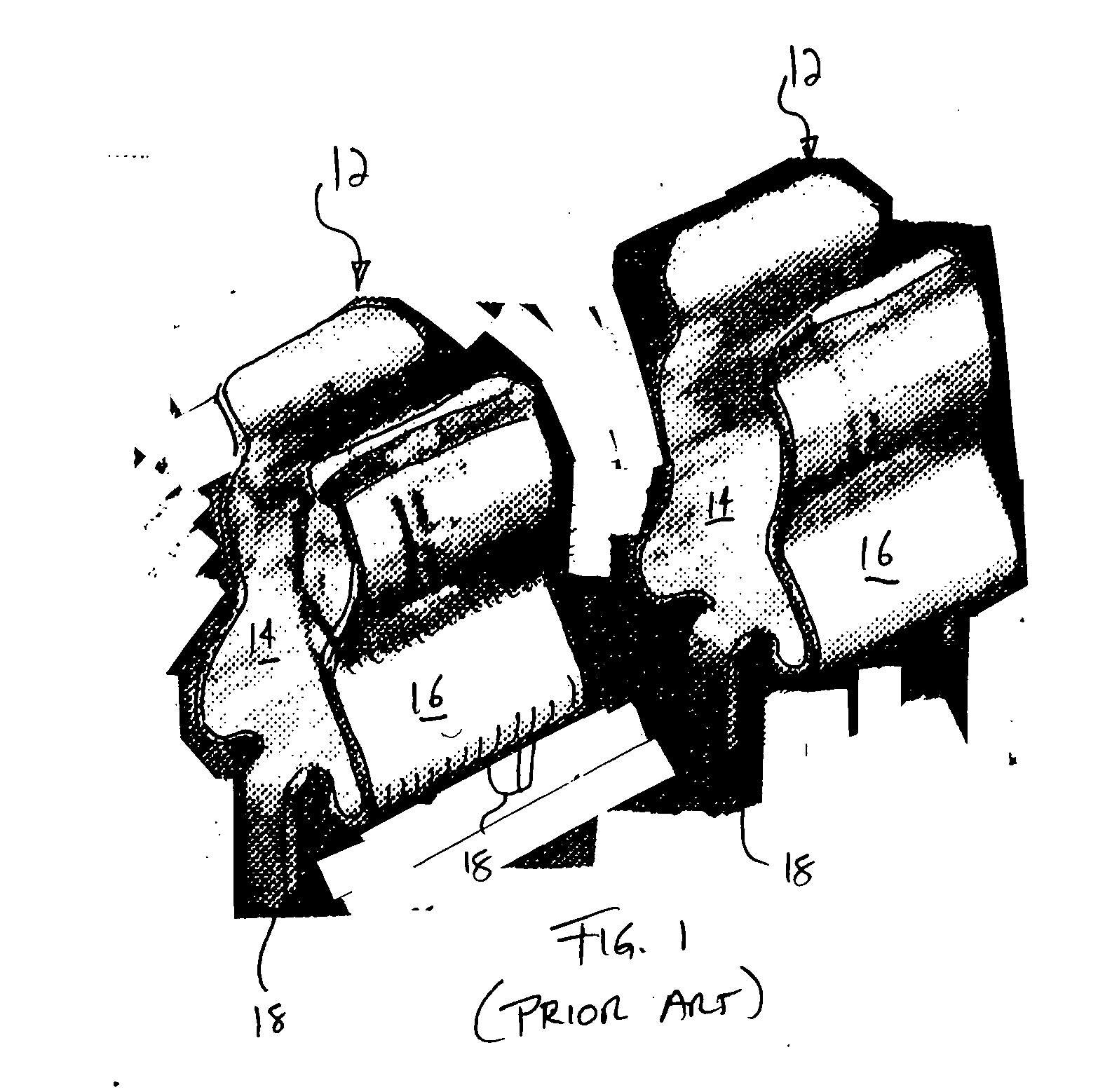
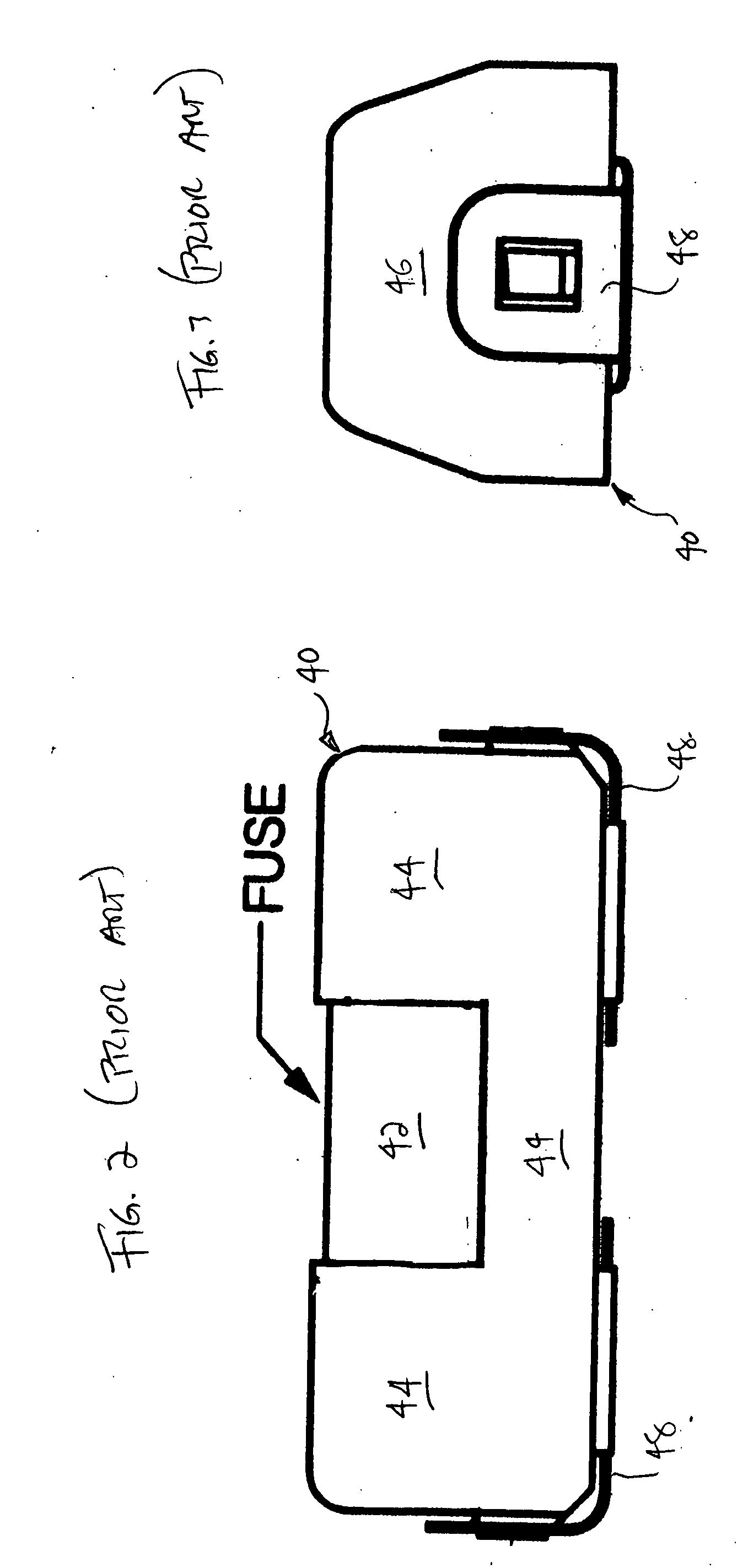
[0031] The present invention provides an improved electrical device. More specifically, the present invention provides an improved PCB fuse assembly, fuse clip and fuse. In one aspect, subminiature fuses are soldered to a PCB via clips attached to the fuse end caps. The clips are physically attached to the PCB pads, enabling the fuse to be replaced if needed and providing thermal decoupling between the fuse and the heating sinking solder / PCB pads. The fuse and clips can also be picked and placed in one operation. In another aspect, improved fuse clips are provided that include tabs that separate the housing portions of the clips from the heating sinking solder / PCB pads. Such improved clips further enhance thermal decoupling. In a further aspect, an improved fuse is provided, in which the thermal decoupling tabs just described are provided directly with the fuse.

[0032] Referring now to the drawings and in particular to FIGS. 4 to 6, various embodiments for thermally decoupled fuse c...


PUM


Abstract

In one aspect of the present invention, subminiature fuses are soldered to a PCB via clips attached to the fuse end caps. The clips are physically attached to the PCB pads, enabling the fuse to be replaced if needed and providing thermal decoupling between the fuse and the heating sinking solder/PCB pads. The fuse and clips can also be picked and placed in one operation. In another aspect, improved fuse clips are provided that include tabs that separate the housing portions of the clips from the heating sinking solder/PCB pads. Such improved clips further enhance thermal decoupling. In a further aspect, an improved fuse is provided, in which the thermal decoupling tabs just described are provided directly with the fuse. In yet a further aspect, a thermally insultive fuse body is provided to further decouple the fuse element from its surroundings.

Description

BACKGROUND OF THE INVENTION [0001] The present invention relates to circuit protection and more particularly to fuse protection. Miniature cartridge fuses commonly include a main insulating housing, conductive end caps secured to the housing and a fuse element or wire extending across the end caps. The cup-shaped or open end caps include a skirt portion that extends over the ends of the housing. The fuse element may be electrically and physically secured to the end caps via a body of solder in each of the end caps. The solder can also extend into small clearance spaces between the skirt of the end caps and the electrically insulative housing. [0002] Miniature or subminiature cartridge fuses are typically soldered directly to a printed circuit board (“PCB”) via a process called reflow soldering. The miniature fuse is typically picked and placed onto conductive pads of the PCB, which have been coated or printed with a solder paste. The PCB carrying the fuse is sent through an oven cal...

Claims


Application Information

Patent Timeline
Patent Type & Authority Applications(United States)
IPC IPC(8): H01H85/02H01H85/04
CPCH01H85/0418H01H85/202H01H2085/0414H01H2085/2085H05K3/301H05K3/3426H05K2201/062H05K2201/10181H05K2201/1031H05K2201/10386H05K2201/10636H05K2201/10757H05K2201/10946Y02P70/50
Inventor WHITNEY, STEPHEN J.DIETSCH, GORDON T.TRAN, VINCENT MINH-TU
Owner LITTELFUSE INC
Why Eureka
Try Eureka