Blue Noise Spatial Temporal Multiplexing

a spatial temporal multiplexing and blue noise technology, applied in the field of digital display systems, can solve the problems of difficult to create small intensity resolution steps, and difficult to achieve small intensity resolution steps. achieve the effect of smooth transition

Inactive Publication Date: 2006-09-07
TEXAS INSTR INC
View PDF11 Cites 10 Cited by
  • Summary
  • Abstract
  • Description
  • Claims
  • Application Information

AI Technical Summary

Benefits of technology

[0024] Another embodiment of the claimed invention provides a method of smoothly transitioning to a display bit period. The method comprising: receiving an input intensity data value for a pixel; allocating the input intensity data value between a binary portion and a fractional portion; comparing the fractional portion to a threshold value to determine at least one fractional display bit; and enabling the pixel during display periods corresponding to the fractional display bits and bits representing the binary portion, wherein the allocating results in a dithering allocation between at least two display bits as a magnitude of the received input intensity data value increases.

Problems solved by technology

One problem encountered by PWM display systems is the difficulty in creating very small intensity resolution steps.
As the contrast ratio of the display system increases, it becomes much more difficult to create small enough steps between intensity levels.
While a one least significant bit (LSB) intensity step is not generally objectionable when the image being displayed is very bright, it can be very objectionable in a dim region of an image.
Unfortunately, the LSB intensity step size cannot be made arbitrarily small.
Very small LSB periods are limited by the amount of data that can be loaded during the frame period or portion thereof.
Additionally, the display device itself has some finite response time.
For example, digital micromirror devices require not only a certain amount of time to load the memory array underlying the mirror array, but also a finite amount of time to reset the mirrors and allow them to transition from one position to the next.
Another problem encountered by PWM display systems is the creation of visual artifacts that arise due to the generation of an image as a series of discrete bursts of light.
PWM temporal artifacts are created when the distribution of radiant energy is not constant over an entire frame period and may be noticeable when there is motion in a scene or when the eye moves across a scene.
When viewed at a normal viewing distance, the PWM contouring artifact created by two adjacent pixels is very difficult, if not impossible, for the typical viewer to detect.
Unfortunately, bit splitting increases the necessary bandwidth of the modulator input since some of the data must be loaded into the system multiple times during a single frame period.

Method used


Image

  • Blue Noise Spatial Temporal Multiplexing
  • Blue Noise Spatial Temporal Multiplexing
  • Blue Noise Spatial Temporal Multiplexing

Examples


Embodiment Construction

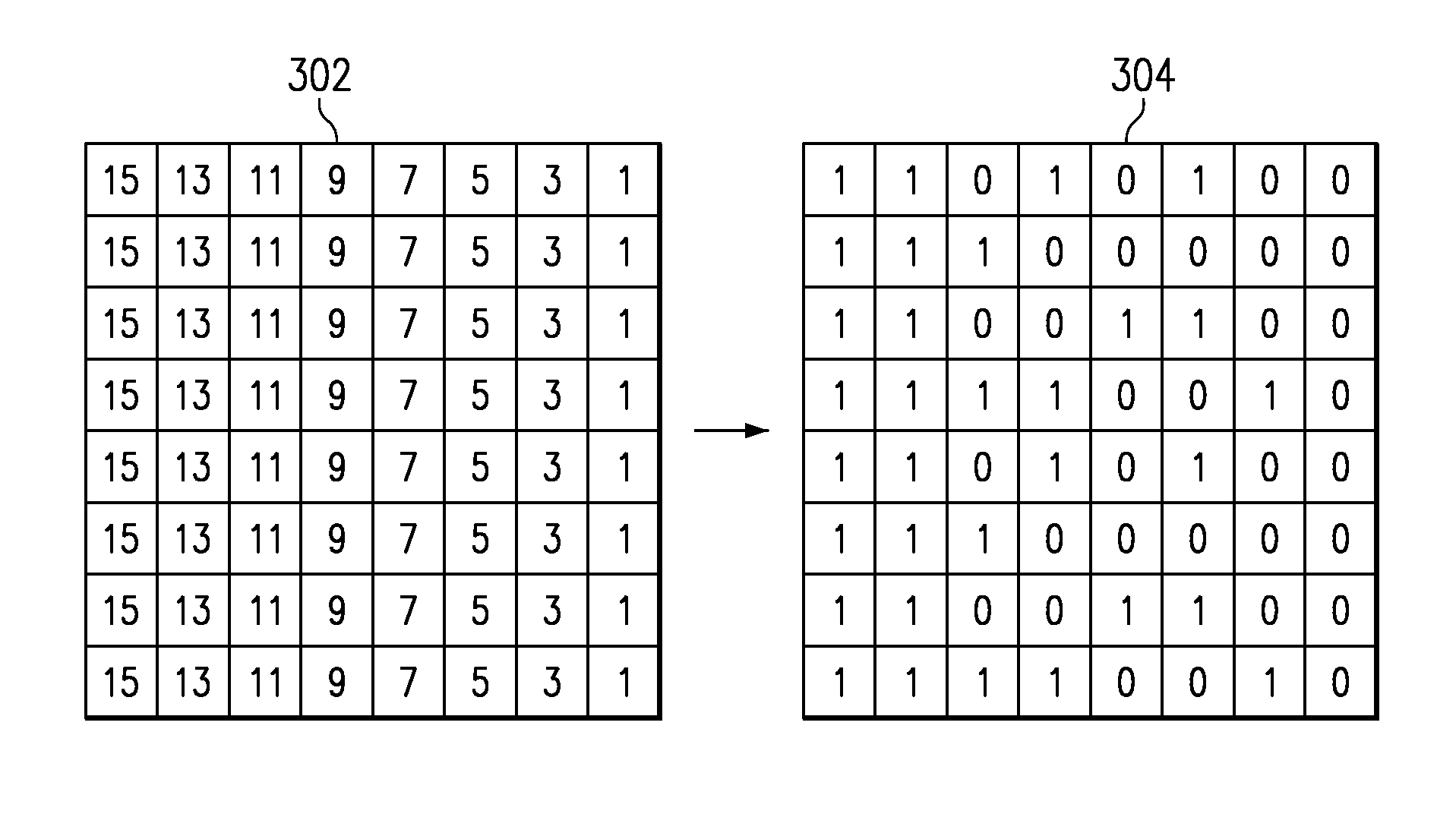
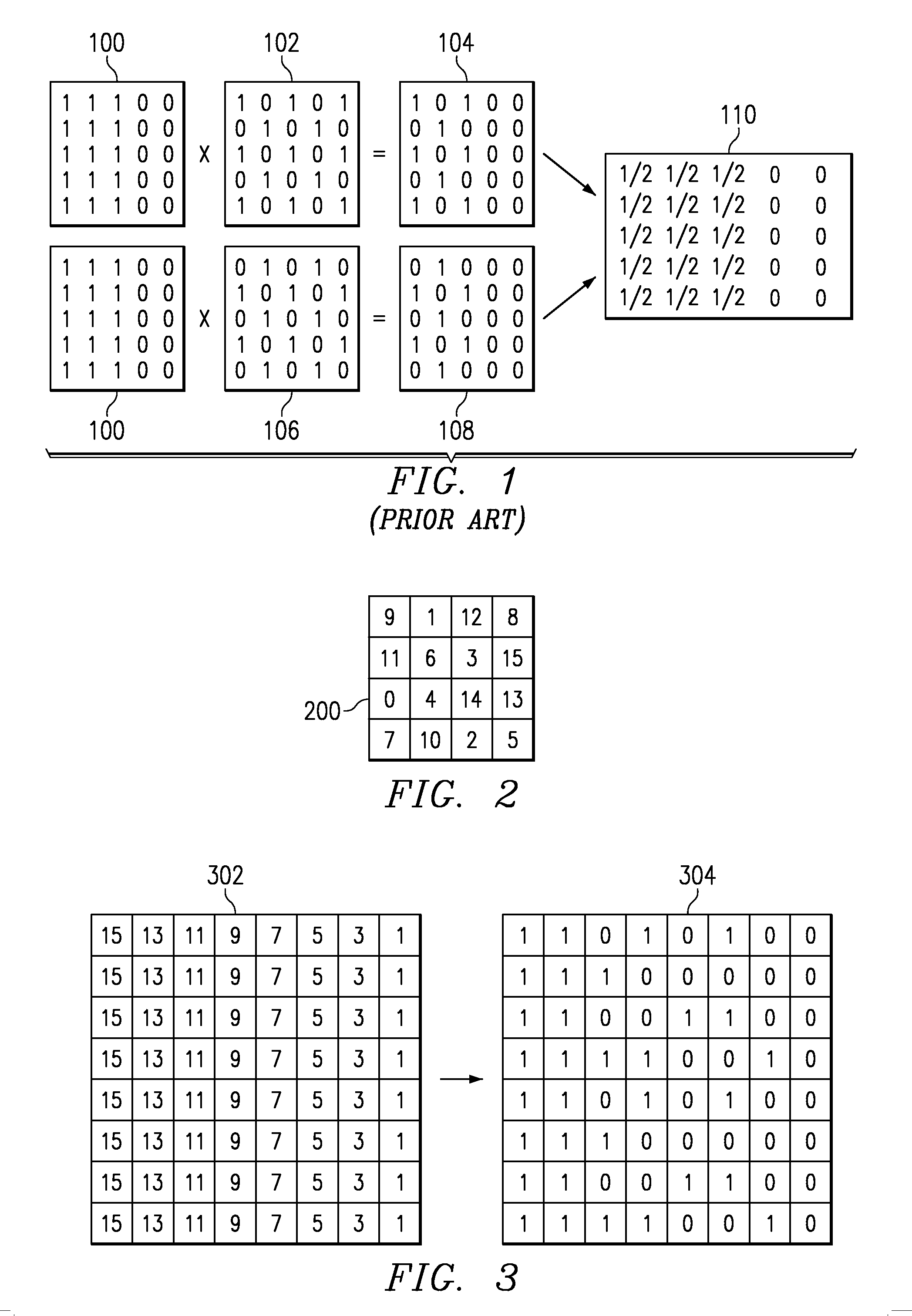
[0031] A new pulse width modulation display method has been developed that greatly reduces the PWM quantization and temporal contouring errors associated with prior PWM display systems. The new method allows much finer control of fractional display bits, virtually eliminating noticeable quantization contouring. The new method also enables each successive higher order bit to be gradually phased in to reduce PWM temporal contouring. The new method relies on a large multi-level mask to reduce the duty cycle of the fractional bits. Preferably the multi-level mask does not have a low-frequency component so that the eye is unable to detect the mask. Preferably the mask is altered, by changing the mask values and / or moving the mask relative to the image, at a rate high enough to avoid detection of the mask.

[0032] As discussed above, typical PWM display systems individually control the duty cycle of each pixel to form an image. At any given time, each pixel of the display typically can onl...


PUM


Abstract

A method and system for performing spatial temporal multiplexing using a multi-threshold mask. A mask generator (404) outputs a threshold value for each pixel of a display. The mask generator typically creates a blue noise mask for a given pixel array that is replicated over the face of the entire display. The blue noise mask generator (404) typically is implemented as a memory lookup table. An index generator (402) provides an offset into the memory lookup table that allows the table to be shifted from time to time. The output of the blue noise mask generator (404), which may be the threshold value itself or a signal representing which threshold is being used, is an input to a selective inverter (406). The selective inverter (406) provides the option of inverting the blue noise mask. To reduce artifacts, the mask is periodically shifted and / or inverted. The value from the mask generator (404), whether inverted or not, is compared to the LSBs of the input data word to yield the fractional bit values. The data adjust block (410) receives the LSBs of the input data word and apportions the intensity between the various fractional bits and perhaps one or more binary bit. Allocating the data between the fractional and binary bits allows the gradual feathering in of each more significant bit as the image intensity word increases.

Description

[0001] This application claims priority from under 35 U.S.C. §119(e)(1) of provisional application No. 60 / 184,949 filed Feb. 25, 2000. CROSS-REFERENCE TO RELATED APPLICATIONS [0002] The following patents and / or commonly assigned patent applications are hereby incorporated herein by reference: Patent No. Filing Date Issue Date Title [0003] U.S. Pat. No. 5,616,228 Jun. 5, 1996 Apr. 8, 1997 Method For Reducing Temporal Artifacts in Digital Video [0004] Ser. No. 09 / 088,674 Jun. 2, 1998 Boundary Dispersion For Mitigating PWM Temporal Contouring Artifacts In Digital Displays [0005] Ser. No. 09 / 572,470 May 17, 2000 Spoke Light Recapture In Sequential Color Imaging Systems [0006] Ser. No. 09 / 573,109 May 17, 2000 Mitigation Of Temporal PWM Artifacts [0007] TI-30641 Herewith Contour Mitigation Using Parallel Blue Noise Dithering SystemFIELD OF THE INVENTION [0008] This invention relates to the field of display systems, more particularly to digital display systems using pulse width modulation...

Claims


Application Information

Patent Timeline
Patent Type & Authority Applications(United States)
IPC IPC(8): G09G5/02G09G3/20
CPCG09G3/20G09G3/2018G09G3/2051G09G2320/0261
Inventor MORGAN, DANIEL J.KEMPF, JEFFREY
Owner TEXAS INSTR INC
Why Eureka
Try Eureka