Discontinuous or variable thickness gain modification coating for projection film and method for making same

Active Publication Date: 2006-09-07
AVERY DENNISON CORP
View PDF79 Cites 14 Cited by
  • Summary
  • Abstract
  • Description
  • Claims
  • Application Information

AI Technical Summary

Benefits of technology

[0008] The present invention is directed to projection films and methods of making the same. In one embodiment, the present invention relates to a projection film whereby the microspheres exhibit improved alignment on the light exit surface and have alignment on the light entrance surface that varies according to the individual microsphere diameter. In another embodiment, the present invention relates to a projection film that provides for variable gain within a single projection film. In another embodiment, the present invention relates to a projection film construction that

Problems solved by technology

Generally, rear projection screens and monitors suffer from poor angularity resulting in difficulties in viewing a projected image unless the viewer is facing the viewing area of such a screen or monitor head-on.
Another drawback associated with conventional processing of microspheres having varying diameters is that the light absorbing layer 14, which is generally made up of a black thermoadhesive coating, may wick up the sides of the smaller microspheres (e.g., 16A, 16C, 16E, 16G, and 16H) dur

Method used


Image

  • Discontinuous or variable thickness gain modification coating for projection film and method for making same
  • Discontinuous or variable thickness gain modification coating for projection film and method for making same
  • Discontinuous or variable thickness gain modification coating for projection film and method for making same

Examples


Example

EXAMPLE 1

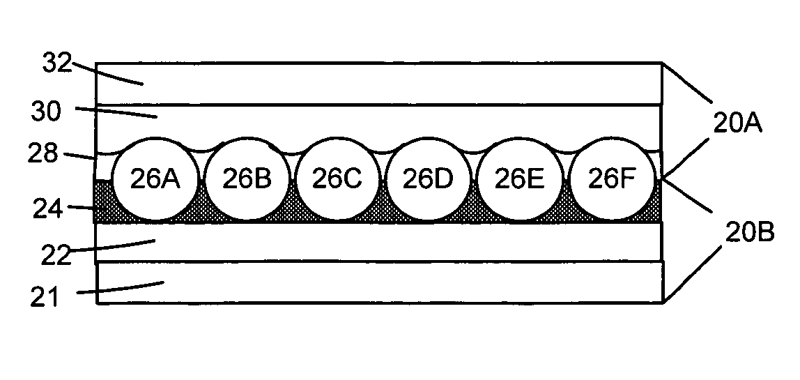
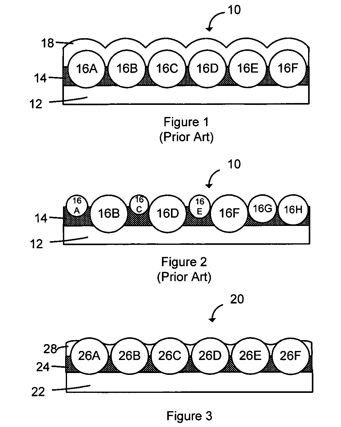
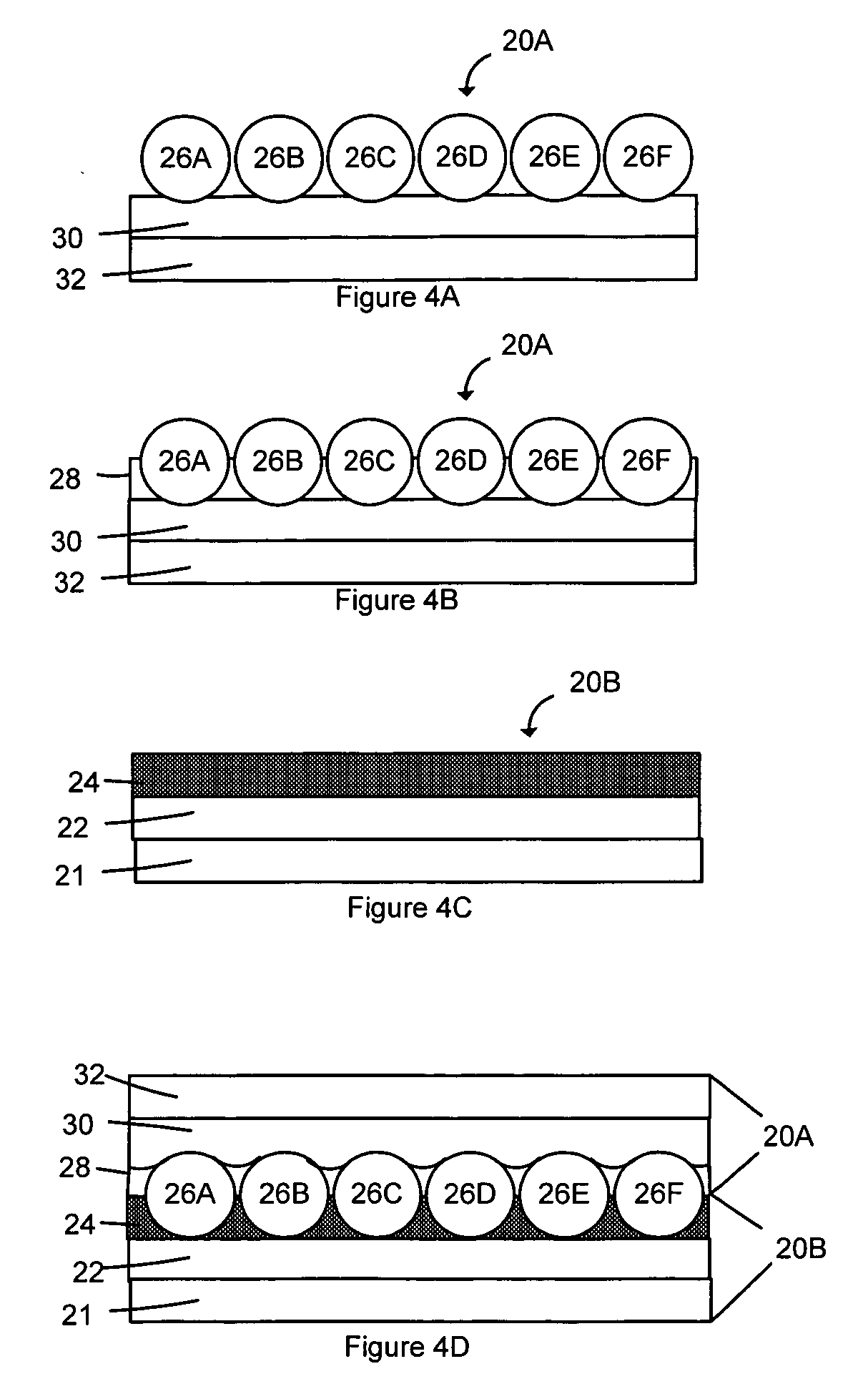
[0057] A first substrate is provided that includes a 75 micron (3 mil) layer of polyethylene terephthalate (SH-71 Polyester film from SKC America) laminated to a 50 micron (2 mil) layer of polymethylmethacrylate (Acrylic HI-7 from ICI). A 15 micron (0.6 mil) layer of black polyvinyl butyral (Butvar B-90 from Solutia containing 3% carbon black) is deposited above the polymethylmethacrylate. Glass microspheres having a varying refractive index of about 1.4 to 2.0 and having an average diameter varying from 40-70 microns are beaded on the polyvinylbutyral layer of the first substrate. A second substrate is provided that includes a 150 micron paper facestock coated with a 37.5 micron low density polyethylene (e.g., Felix Schoeller Technical Paper F315L). The first and second constructions are pressed together (laminated) (black polyvinylbutyral layer with exposed microspheres of construction 1 to the low density polyethylene layer of construction 2) at a temperature of 285° F....

Example

EXAMPLE 2

[0058] A first substrate is provided that includes a 150 micron (6 mil) layer of polyethylene terephthalate (SH-71 Polyester film from SKC America) laminated to a 37.5 micron (1.5 mil) layer of pigmented low density polyethylene is beaded with glass microspheres having a varying refractive index of about 1.4 to 2.0 and having an average diameter varying from 40-70 microns. A second substrate is provided that includes a 50 micron (2 mil) layer of polyethylene terephthalate (SH-71 Polyester film from SKC America), a 30 micron (1.2 mil) of clear Urethane and 15 micron (0.6 mil) layer of black polyvinyl butyral (Butvar B-90 from Solutia containing 3% carbon black) is deposited above the clear Urethane. The first and second constructions are pressed together (laminated) (black polyvinylbutyral layer with clear Urethane of construction 2 to the low density polyethylene layer with exposed microspheres of construction 2) at a temperature of 285° F. (140° C.) and 100 psi using a ro...


PUM

PropertyMeasurementUnit
Thicknessaaaaaaaaaa
Thicknessaaaaaaaaaa
Diameteraaaaaaaaaa

Abstract

The present invention relates to projection films and methods of making the same. In particular, the present invention relates to a projection film whereby the microspheres exhibit improved alignment on the light exit surface and have alignment on the light entrance surface that varies according to the individual microsphere diameter. In another embodiment, the present invention relates to a projection film that has the attributes of variable gain within the single projection film. In another embodiment, the present invention relates to an exposed microsphere projection film construction that provides modification of the head-on and angular pattern of light transmission (gain).

Description

FIELD OF THE INVENTION [0001] The present invention relates to projection films for rear projection screens and the like, including monitors and methods of making same, and particularly to projection films exhibiting improved microsphere alignment on the light exit surface and projection films with variable gain within a single projection film. BACKGROUND OF THE INVENTION [0002] Projection films are used with rear projection screens and monitors for transmitting an image generated by a projector or the like located at the back of the screen to the viewer on the opposite side of the screen. The viewable image is generally affected by the amount of light transmitted through the screen. Generally, the construction of rear projection screens and monitors limit the amount of light transmitted through the screen or monitor to the viewer. It is thus desirable to have constructions that provide increased light throughput. [0003] Generally, rear projection screens and monitors suffer from po...

Claims


Application Information

Patent Timeline
IPC IPC(8): G03B21/60
CPCG03B21/602Y10T428/26G02B1/11G02B6/003G02B6/004G03B21/625G02B30/27
Inventor HANNINGTON, MICHAEL E.
Owner AVERY DENNISON CORP
Why Eureka
Try Eureka