[0017] The present invention is directed to a
system that facilitates controlled fusion in a
magnetic field having a field-reversed topology and the direct conversion of fusion product energies to
electric power. The system, referred to herein as a plasma-
electric power generation (PEG) system, preferably includes a fusion reactor having a containment system that tends to substantially reduce or eliminate anomalous transport of ions and electrons. In addition, the PEG system includes an energy conversion system coupled to the reactor that directly converts fusion product energies to
electricity with high efficiency.
[0018] In one embodiment, anomalous transport for both ions and electrons tends to be substantially reduced or eliminated. The anomalous transport of ions tends to be avoided by magnetically confining the ions in a
magnetic field of
field reversed configuration (FRC). For electrons, the anomalous transport of energy is avoided by tuning an externally applied magnetic field to develop a strong
electric field, which confines the electrons electrostatically in a deep
potential well. As a result, fusion fuel plasmas that can be used with the present confinement apparatus and process are not limited to neutronic fuels, but also advantageously include advanced or aneutronic fuels. For aneutronic fuels, fusion
reaction energy is almost entirely in the form of charged particles, i.e., energetic ions, that can be manipulated in a magnetic field and, depending on the fuel, cause little or no radioactivity.
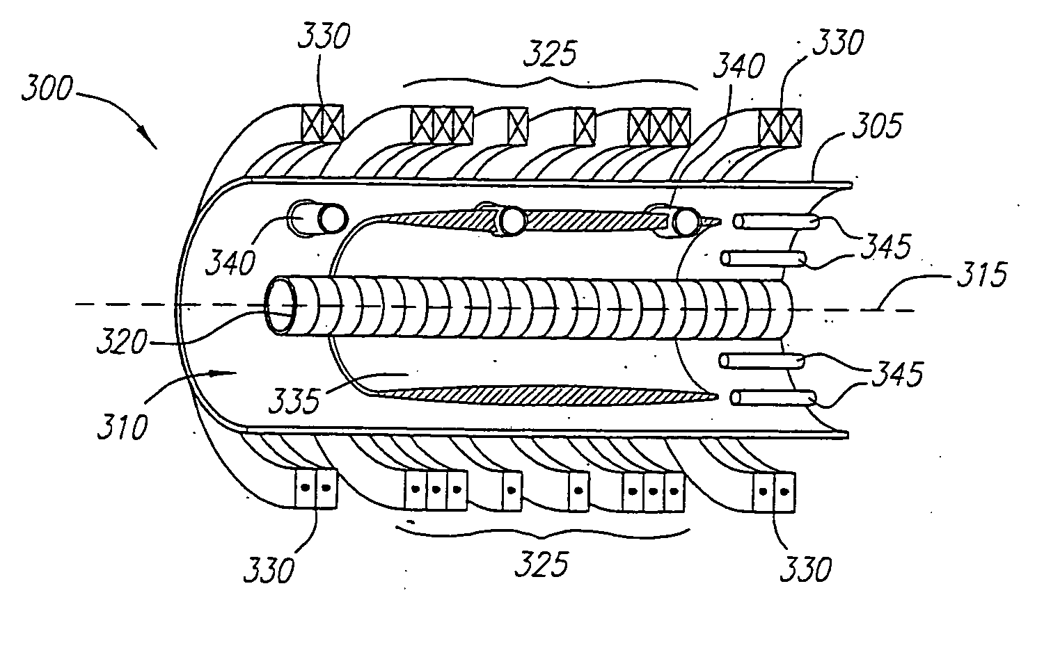
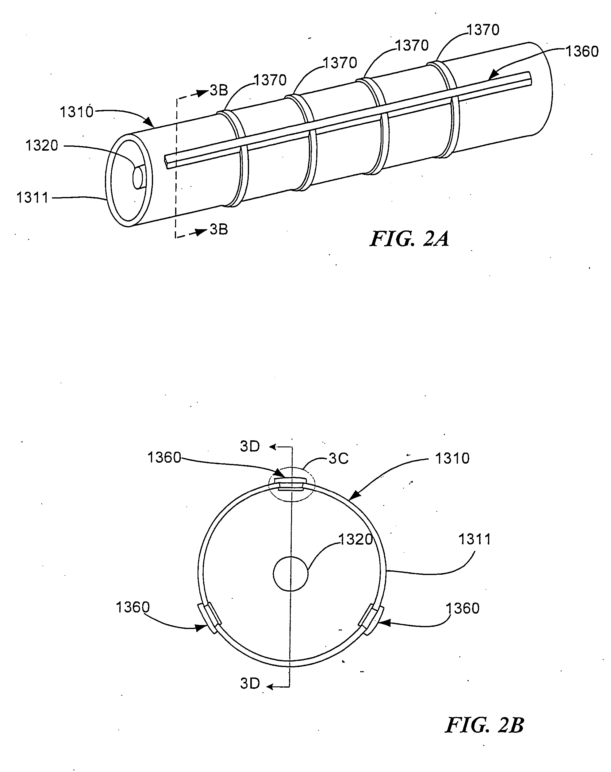
[0019] In a preferred embodiment, a fusion reactor's plasma containment system comprises a chamber, a magnetic field generator for applying a magnetic field in a direction substantially along a principle axis, and an annular plasma layer that comprises a circulating beam of ions. Ions of the annular
plasma beam layer are substantially contained within the chamber magnetically in orbits and the electrons are substantially contained in an electrostatic energy well. In one preferred embodiment the magnetic field generator includes a current coil. Preferably, the magnetic field generator further comprises mirror coils near the ends of the chamber that increase the magnitude of the applied magnetic field at the ends of the chamber. The system also comprises one or more beam injectors for injecting neutralized
ion beams into the magnetic field, wherein the beam enters an
orbit due to the force caused by the magnetic field. In a preferred embodiment, the system forms a magnetic field having a topology of a field reversed configuration.
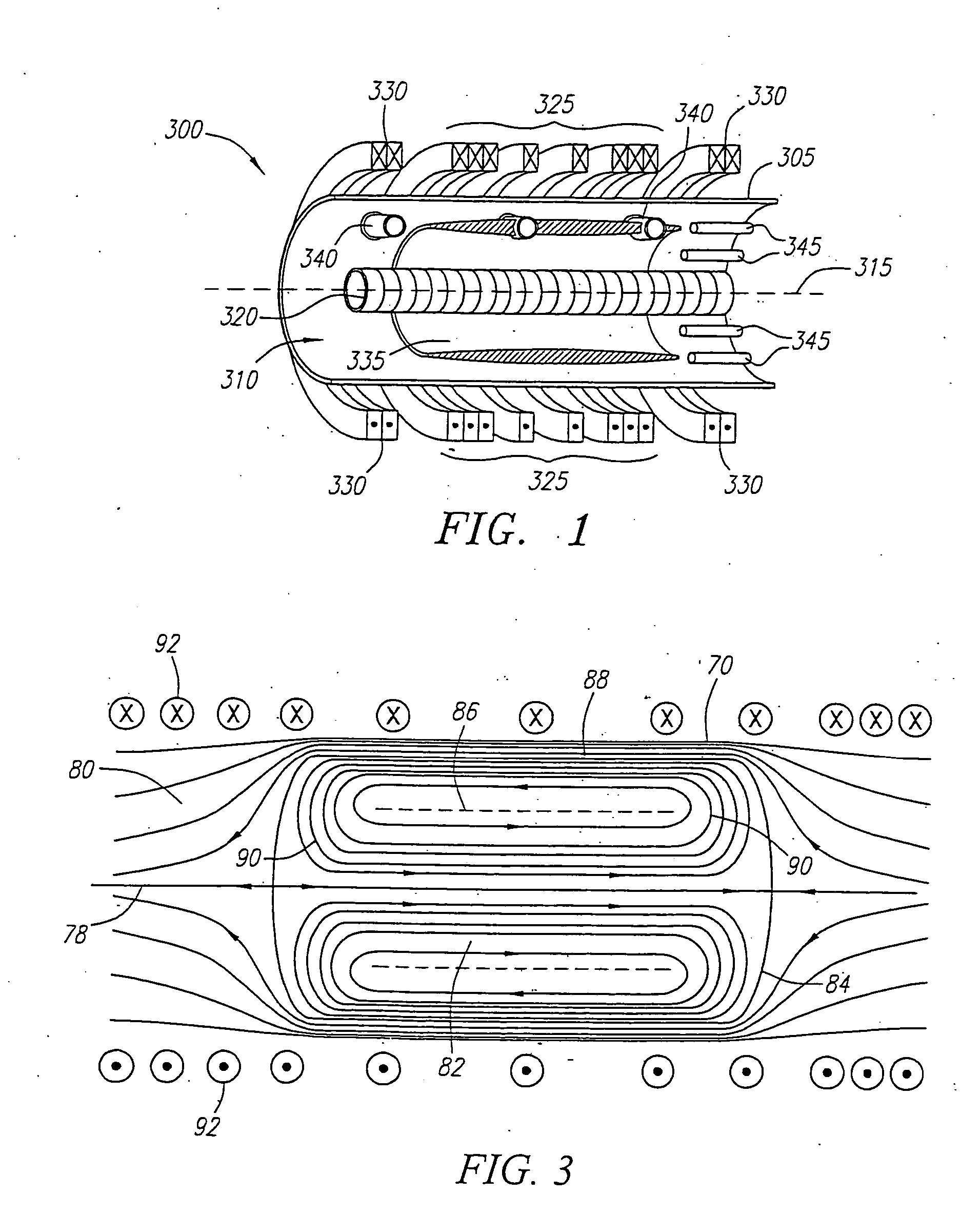
[0020] In another preferred embodiment, an alternative chamber is provided that prevents the formation of azimuthal image currents in a
central region of the chamber wall and enables
magnetic flux to penetrate the chamber on a fast timescale. The chamber, which is primarily comprised of stainless steel to provide structural strength and good vacuum properties, includes axial insulating breaks in the chamber wall that run along almost the entire length of the chamber. Preferably, there are three breaks that are about 120 degrees apart from each other. The breaks include a slot or gap formed in the wall. An insert comprising an insulating material, preferably a
ceramic or the like, is inserted into the slots or gaps. In the interior of the chamber, a
metal shroud covers the insert. On the outside of the chamber, the insert is attached to a sealing panel, preferable formed from fiberglass or the like, that forms a vacuum barrier by means of an O-ring seal with the stainless steel surface of the chamber wall.
[0021] In yet another preferred embodiment, an inductive plasma source is mountable within the chamber and includes a shock coil
assembly, preferably a single turn shock coil, that is preferably fed by a
high voltage (about 5-15 kV) power source (not shown). Neutral gas, such as
Hydrogen (or other appropriate gaseous fusion fuel), is introduced into the source through direct gas feeds via a Laval
nozzle. Once the gas emanates from the
nozzle and distributes itself over the surface of the coil windings of the shock coil, the windings are energized. The
ultra fast current and flux ramp-up in the
low inductance shock coil leads to a very high
electric field within the gas that causes breakdown,
ionization and subsequent ejection of the formed plasma from the surface of the shock coil towards the center or mid-plane of the chamber.
[0022] In a further preferred embodiment, a RF drive comprises a quadrupolar
cyclotron located within the chamber and having four azimuthally symmetrical electrodes with gaps there between. The
quadrupole cyclotron produces an
electric potential wave that rotates in the same direction as the azimuthal velocity of ions, but at a greater velocity. Ions of appropriate speed can be trapped in this wave, and reflected periodically. This process increases the
momentum and energy of the fuel ions and this increase is conveyed to the fuel ions that are not trapped by collisions.

