Photodetection device and light source module

Inactive Publication Date: 2006-09-07
SUMITOMO ELECTRIC IND LTD
View PDF13 Cites 3 Cited by
  • Summary
  • Abstract
  • Description
  • Claims
  • Application Information

AI Technical Summary

Benefits of technology

[0007] The present invention has been designed in order to solve this problem, and it is an object thereof to provide a photodetection device which can monitor optical power with a greater degree of accuracy even when employed in processing applications and the like.

Problems solved by technology

However, when a conventional light source module such as that described above comprises a light source which outputs light in a plurality of transverse modes, such as a light source used in processing applications and the like, the detection result generated by the photodetection device may vary even when the power of the light output from the light source is constant, and hence monitoring of the power of the light output from the light source may not be performed accurately.

Method used


Image

  • Photodetection device and light source module
  • Photodetection device and light source module
  • Photodetection device and light source module

Examples


Embodiment Construction

[0015] A preferred embodiment of the present invention will be described in detail below with reference to the attached drawings. Note that in the drawings, identical elements have been allocated identical reference numerals, and duplicate description thereof has been omitted.

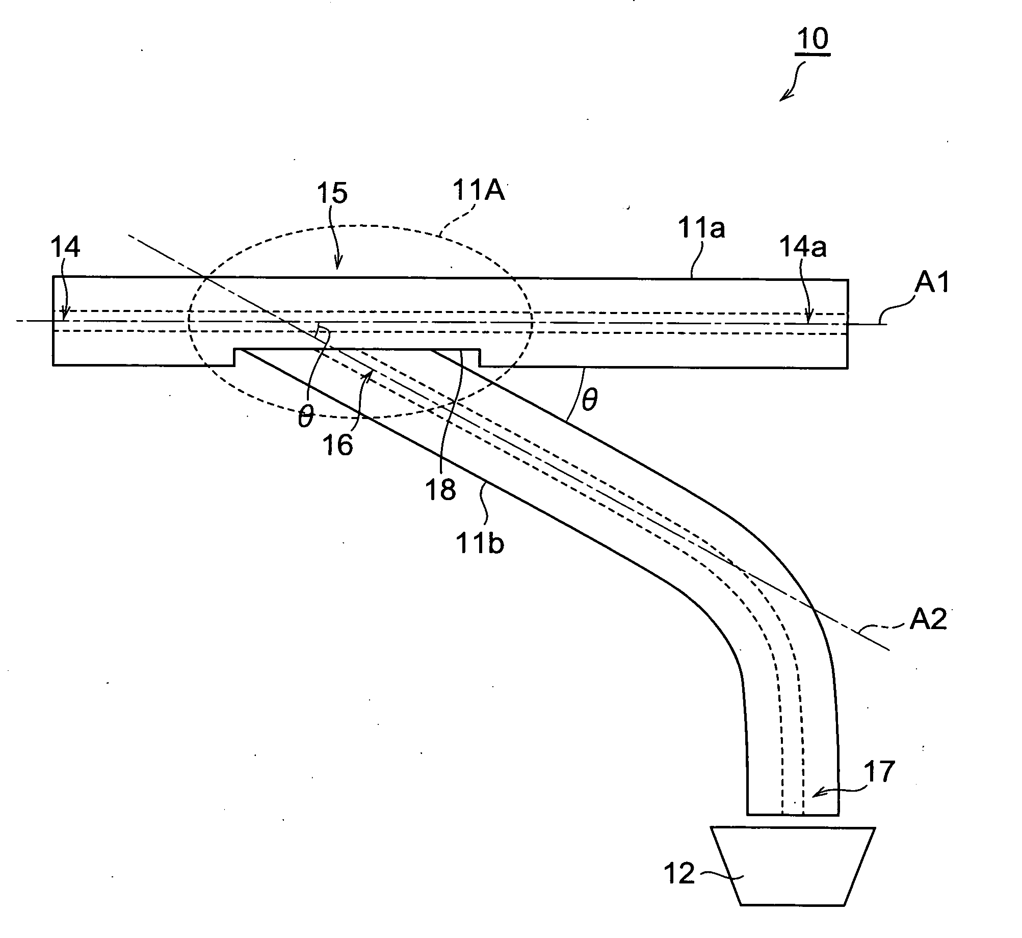
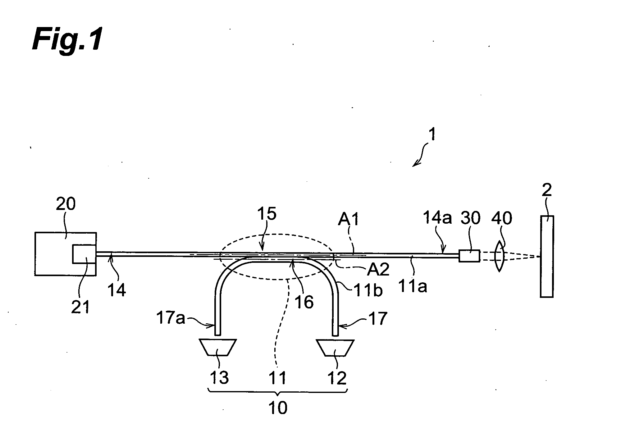
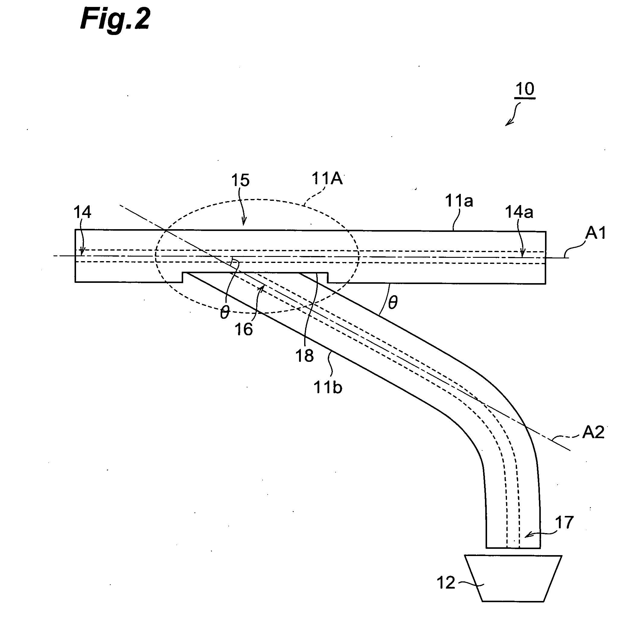
[0016]FIG. 1 is a constitutional diagram of a light source module 1 and a photodetection device 10 according to this embodiment. The light source module 1 shown in the drawing is used to process a processing subject 2 by irradiating the processing subject 2 with laser light, and comprises the photodetection device 10, a light source 20, a collimator 30, and a condenser lens 40. The photodetection device 10 comprises an optical fiber coupler 11, a photodetector 12, and a photodetector 13. The optical fiber coupler 11 is constituted by a first optical fiber 11a and a second optical fiber 11b.

[0017] The light source 20 outputs the laser light with which the processing subject 2 is irradiated. The laser light out...


PUM


Abstract

There is disclosed a photodetection device comprising: a photodetector having detection sensitivity at a first wavelength; a first optical fiber propagating light in a plurality of modes at the first wavelength, the first optical fiber having an entrance end on which light at the first wavelength falls; and a second optical fiber propagating light in a plurality of modes at the first wavelength, the second optical fiber having a product of a core diameter and a numerical aperture at the first wavelength that is greater than a product of a core diameter and a numerical aperture at the first wavelength of the first optical fiber, the second optical fiber having one end and another end, the second optical fiber being optically coupled to the first optical fiber at the middle of the first optical fiber in a longitudinal direction of the first optical fiber, and the one end of the second optical fiber being optically coupled to the photodetector.

Description

BACKGROUND OF THE INVENTION [0001] 1. Field of the Invention [0002] The present invention relates to a photodetection device and a light source module. [0003] 2. Related Background Art [0004] A photodetection device is used to monitor the power of light output from a light source by diverting and extracting a part of the light output from the light source and detecting the power of the extracted light using a photodetector, for example. In this type of photodetection device, an optical fiber coupler is preferably used to divert a part of the light. Note that a photodetection device comprises a photodetector and an optical fiber coupler. A device comprising the photodetection device and a light source is known as a light source module. [0005] An optical fiber coupler is manufactured by subjecting a first optical fiber and a second optical fiber to fusion tapering such that the first optical fiber and second optical fiber are optically coupled to each other. The light source is couple...

Claims


Application Information

Patent Timeline
IPC IPC(8): G02B6/26
CPCG02B6/2826G02B6/2835G02B6/2852G02B6/4201G02B6/4286
Inventor KAKUI, MOTOKI
Owner SUMITOMO ELECTRIC IND LTD
Why Eureka
Try Eureka