
Method for cleaning an industrial part

a technology for industrial parts and cleaning methods, applied in the direction of cleaning processes and equipment, cleaning process and equipment, chemistry apparatus and processes, etc., can solve the problems of pollution of the facility floor, damage to the engine after assembly of individual component parts, and pooling of cutting oils and shavings, so as to prevent the pollution of the conveying means and area

Inactive Publication Date: 2006-09-14
VALIANT CO LTD
View PDF6 Cites 18 Cited by
  • Summary
  • Abstract
  • Description
  • Claims
  • Application Information

AI Technical Summary

Benefits of technology

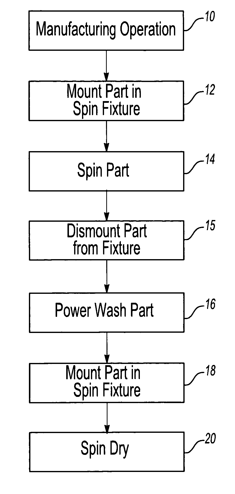
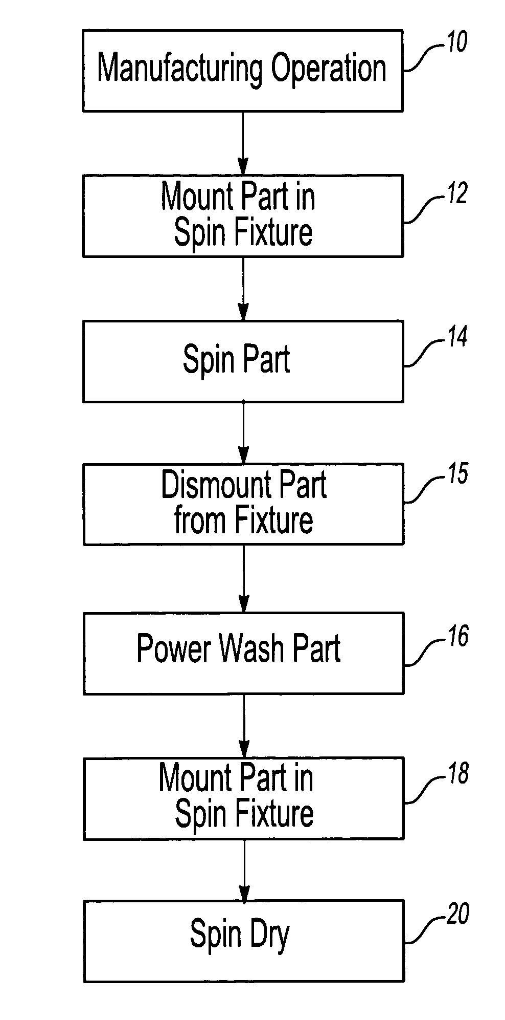
[0011] Following the spinning operation, the part is either conveyed to the next machining operation or subjected to a wash with a cleaning solution which is preferably water based. This cleaning solution is sufficient to remove any remaining manufacturing debris from the industrial part. Both the cleaning solution flow and its pressure can be adjusted to that just necessary, saving initial investment as well as energy cost in production.
[0013] In the first alternative, the part is spun, but not washed, between two intermediate manufacturing operations, thereby preventing the pollution of the conveying means and area, and washed only after the final manufacturing operation.

Problems solved by technology

The failure to integrally remove such debris from each industrial part prior to assembly can result in damage to the engine after assembly of the individual component parts.
One disadvantage of this previously known method of cleaning the parts, however, is that oftentimes the cutting oils and shavings would pool in the areas of the industrial part.
This, in turn, resulted in pollution of the facility floor when conveying the part from one machining operation to the next, and in premature pollution / saturation of the water-based washing solution.
A still further disadvantage of these previously known methods to clean industrial parts is that, in some cases, the water spray was insufficient to remove all of the manufacturing debris, such as metal shavings, oil and coarse sand, from the part during the cleaning operation, when accumulating in too high quantity.
When this happened, the unremoved debris can damage the engine after final assembly.
A still further disadvantage of the previously known methods for cleaning industrial parts is that very high water pressure is employed, particularly when the parts are heavily contaminated.
Such high pressure water disadvantageously results in excessive noise and power consumption.
Furthermore, such high pressure water sources typically have elevated water temperatures due to the mechanism for producing the high pressure (Joules effect) which in turn heats the parts.
When this happens, it may be necessary to cool the washed parts in a refrigerated trough which further increases energy consumption.

Method used


Image

  • Method for cleaning an industrial part
  • Method for cleaning an industrial part

Examples


Embodiment Construction

[0015] With reference to the drawing, at step 10 the metal part is subjected to a manufacturing operation of some sort. This manufacturing operation can include casting, machining, and / or the like.

[0016] Following the manufacturing operation at step 10, manufacturing debris remains on the part. This debris can include sand, cutting oils, metal shavings, and / or the like. Such manufacturing debris must be removed from the part prior to assembly of the part in the final machine.

[0017] Following the manufacturing operation at step 10, the part is then mounted in a spin fixture at step 12. The actual construction for the spin fixture will vary from one part to another.

[0018] After the part is mounted in a spin fixture at step 12, the part is then spun at step 14 for a time period and at a speed sufficient to eject at least a portion, and preferably most, of the manufacturing debris from the part. In practice, the part is spun at a speed of between 150 and 500 revolutions per minute an...


PUM


Abstract

A method for cleaning an industrial part, such as crankshafts, engine blocks and the like, following a manufacturing operation after which manufacturing debris, such as oils, shavings, and / or foundry sand, are present on the part. The part is first spun at a speed and for a time period sufficient to eject at least a portion of the debris and oil from the part after the manufacturing operation. Thereafter, the part is washed with a cleaning solution to remove the remaining oil and debris from the part. Optionally, the part is spun dry after being washed with the cleaning solution.

Description

BACKGROUND OF THE INVENTION [0001] I. Field of the Invention [0002] The present invention relates to a method for cleaning an industrial part following a manufacturing operation. [0003] II. Description of Relevant Art [0004] In the manufacture of machinery, such as the manufacture of automotive engines, it is necessary to clean the parts following the manufacturing operation. Such parts contain not only cutting oils and lubricants from the machining operation, but also machine shavings, coarse sand residue and the like. The failure to integrally remove such debris from each industrial part prior to assembly can result in damage to the engine after assembly of the individual component parts. Furthermore, as used herein, the term “industrial part” means a metallic or plastic component that is subsequently assembled into a machine. [0005] Previously, in order to clean the industrial part of debris, the industrial part was subjected to high pressure liquid sprays which directed a cleani...

Claims


Application Information

Patent Timeline
Patent Type & Authority Applications(United States)
IPC IPC(8): B08B5/04B08B7/00B08B3/00
CPCB08B3/02
Inventor SOLCZ, MARTYNOESTHEDEN, ANDREW
Owner VALIANT CO LTD
Learn More