Multiple side draws during distillation in the production of base oil blends from waxy feeds

a technology of waxy feed and distillation process, which is applied in the direction of petroleum wax refining, hydrocarbon oil treatment products, lubricating oil distillation, etc., can solve the problems of poor low temperature properties of feedstocks at the star

Inactive Publication Date: 2006-09-14
CHEVROU USA INC
View PDF8 Cites 85 Cited by
  • Summary
  • Abstract
  • Description
  • Claims
  • Application Information

AI Technical Summary

Benefits of technology

[0008] (b) separating the isomerized waxy feed in a vacuum distillation tower, which is alternately operated in a light block mode and in a medium block mode, into at least three base oil fractions having different boiling ranges, whereby at least three grades of base oil are produced in light block mode operation and at least three grades of base oil are produced in medium block mode operation; and (c) blending each grade of base oil produced by the vacuum distillation tower during light block mode operation with the corresponding grade of base oil produced by the distillation tower during medium block mode operation to produce at least three lubricating base oil blends each meeting a target value for at least one pre-selected property. The process scheme is particularly advantageous because it allows the base oil plant to produce pre-selected amounts of one or more grade of base oil. By introducing this flexibility into the operation of the base oil plant the product may be controlled to produce base oil grades to meet current market conditions without the necessity of large capital expenditures for storage tanks.

Problems solved by technology

Since these unconventional waxy feedstocks are primarily composed of normal paraffins (n-paraffins), these feedstocks initially have poor low temperature properties, such as pour point and cloud point.

Method used


Image

  • Multiple side draws during distillation in the production of base oil blends from waxy feeds
  • Multiple side draws during distillation in the production of base oil blends from waxy feeds
  • Multiple side draws during distillation in the production of base oil blends from waxy feeds

Examples


example 1

[0055] A Fischer-Tropsch wax prepared over a cobalt based catalyst was hydrotreated. Upon analysis the boiling range distribution was found to be as shown in Table 1.

TABLE 1Fischer-Tropsch Wax Boiling Range DistributionD-6352 SIMDIST TBP (wt. %)° C.° F.T0.5295563T5342648T10356672T20380716T30402755T50442827T70488911T80516961T905561032T955831082T95.56321170

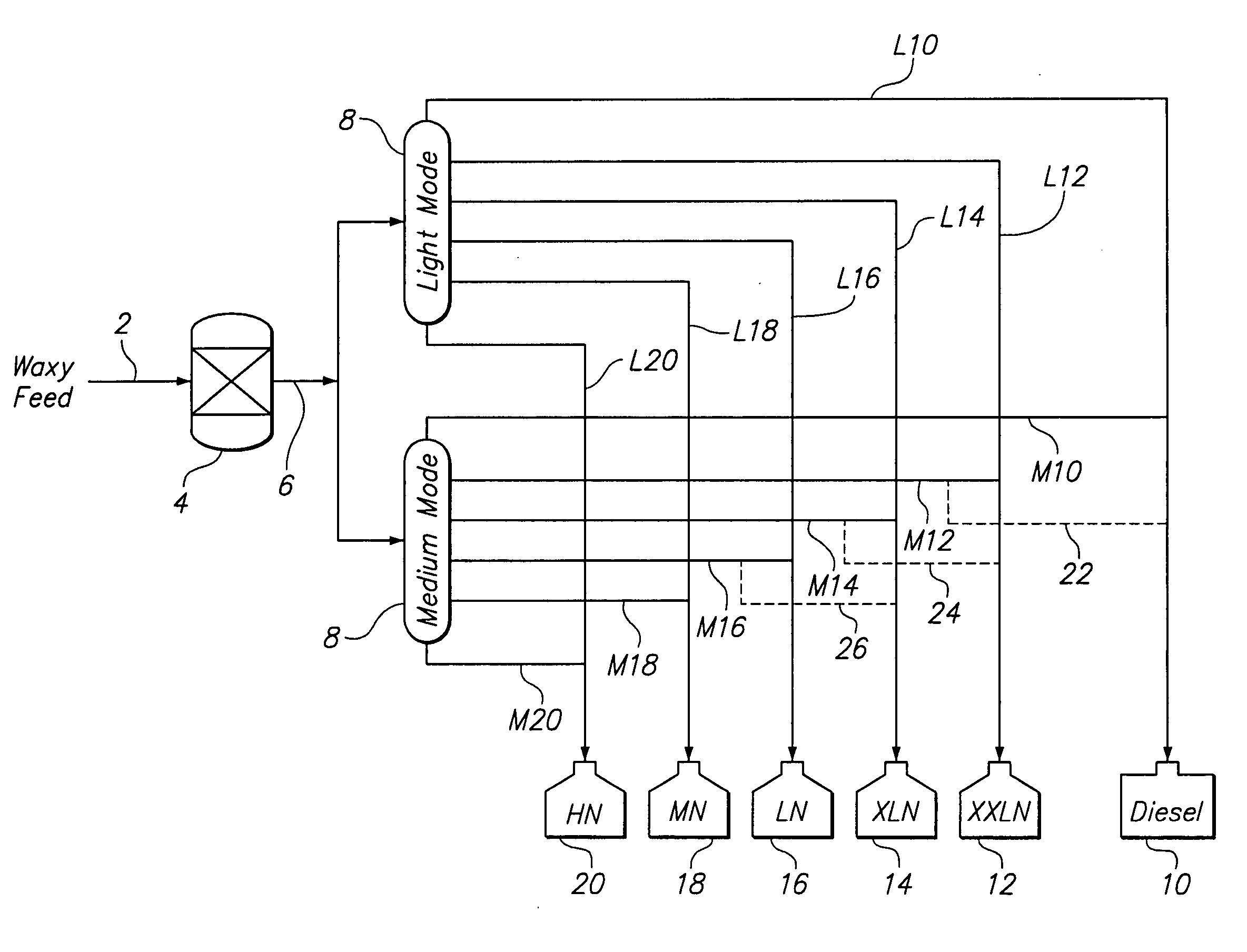
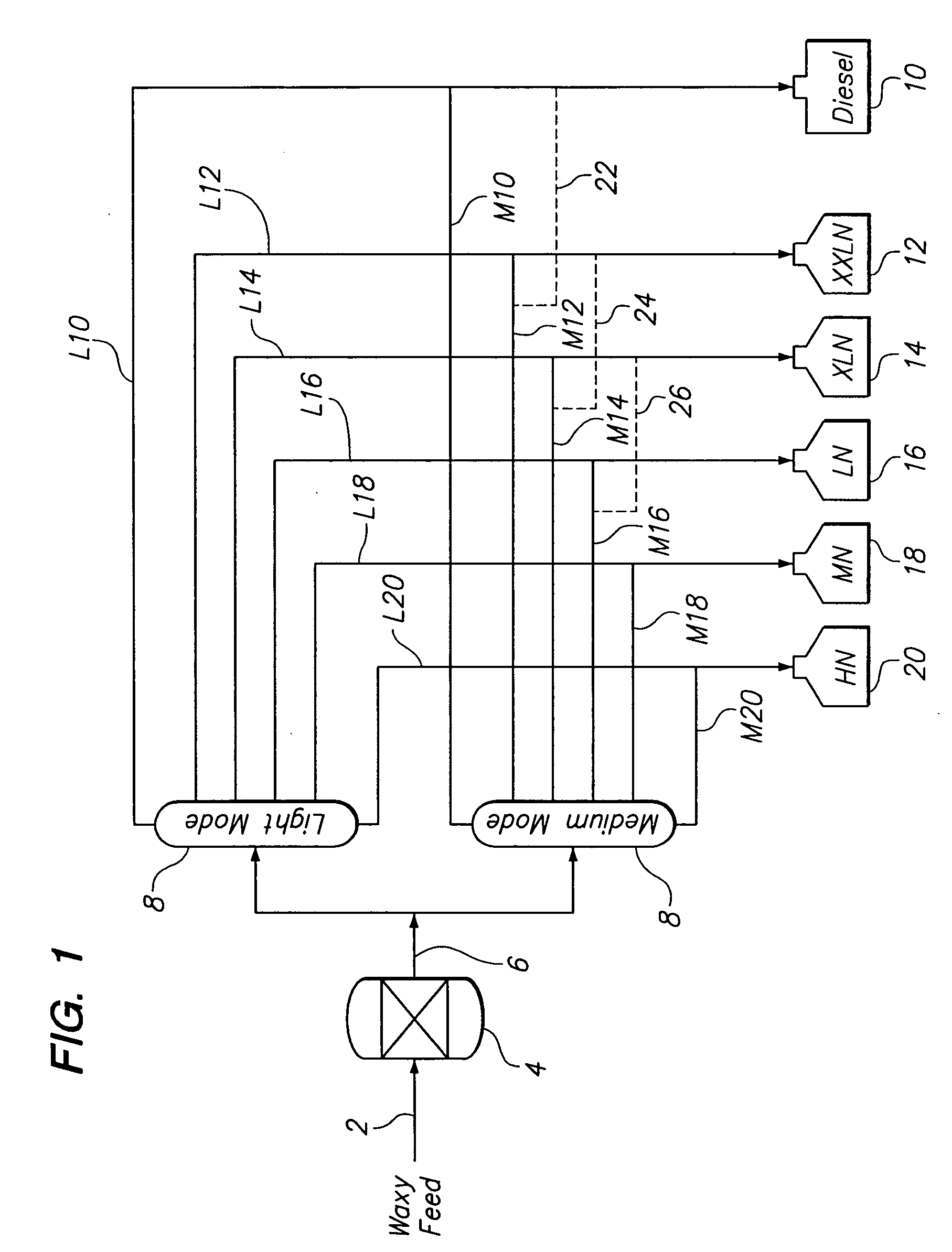
[0056] A broad boiling base oil was made from the Fischer-Tropsch wax described above by hydroisomerizing it over a Pt / SAPO-11 catalyst and subsequently hydrofinishing it over a Pt / Pd on silica-alumina hydrofinishing catalyst. The broad boiling base oil produced, which has a boiling point of 550° F. or above, was subsequently separated in a vacuum distillation tower operated in a light block mode and a medium block mode. The broad boiling base oil was 78.42 wt. % of the total yield of products out of the hydrofinishing reactor. Both distillation modes produced five fractions. The fractions with the highest cut point range in each ...

example 2

[0060] 50 / 50 blends of the fractions from the two different distillation modes in Example 1 were prepared. The distillation cut point ranges, product yields, and product properties produced by the blends are summarized in Table 4, below.

TABLE 450 / 50 Blended Products with Five Fractions50 / 50 BlendsL1 + M1L2 + M2L3 + M3L4 + M4L5 + M5ProductHeavyXLNLNMNHNType or BaseDieselOil GradeDistillation18.3929.1029.7716.656.09Yield, wt. %Gravity,47.643.9541.6540.136.2°APIPour−49−30−24.5−20.5−2Point, ° C.Viscosity1.5912.5874.2717.74821.62at 100° C.,cStViscosity—125143157158IndexNoack97.440.312.81.70Volatility,wt. %

[0061] Note that three of the blended base oil grades in this example had very high VI. The XLN, LN, and MN base oil grades all had a VI greater than the formula 28×Ln(Vis 100)+95.

[0062] When transported and blended together in storage tanks, a full base oil slate is produced. The blend of L1 and M1 was a good quality heavy diesel fuel. The other grades were all useful as base oil pr...

example 3

[0065] The same broad boiling base oil described in Example 1 was separated in a vacuum distillation tower operated in a light block mode and a medium block mode. Each mode produced six, instead of five fractions. As in Example 2, above, the fractions with the highest cut point range in each mode were distillation bottoms fractions.

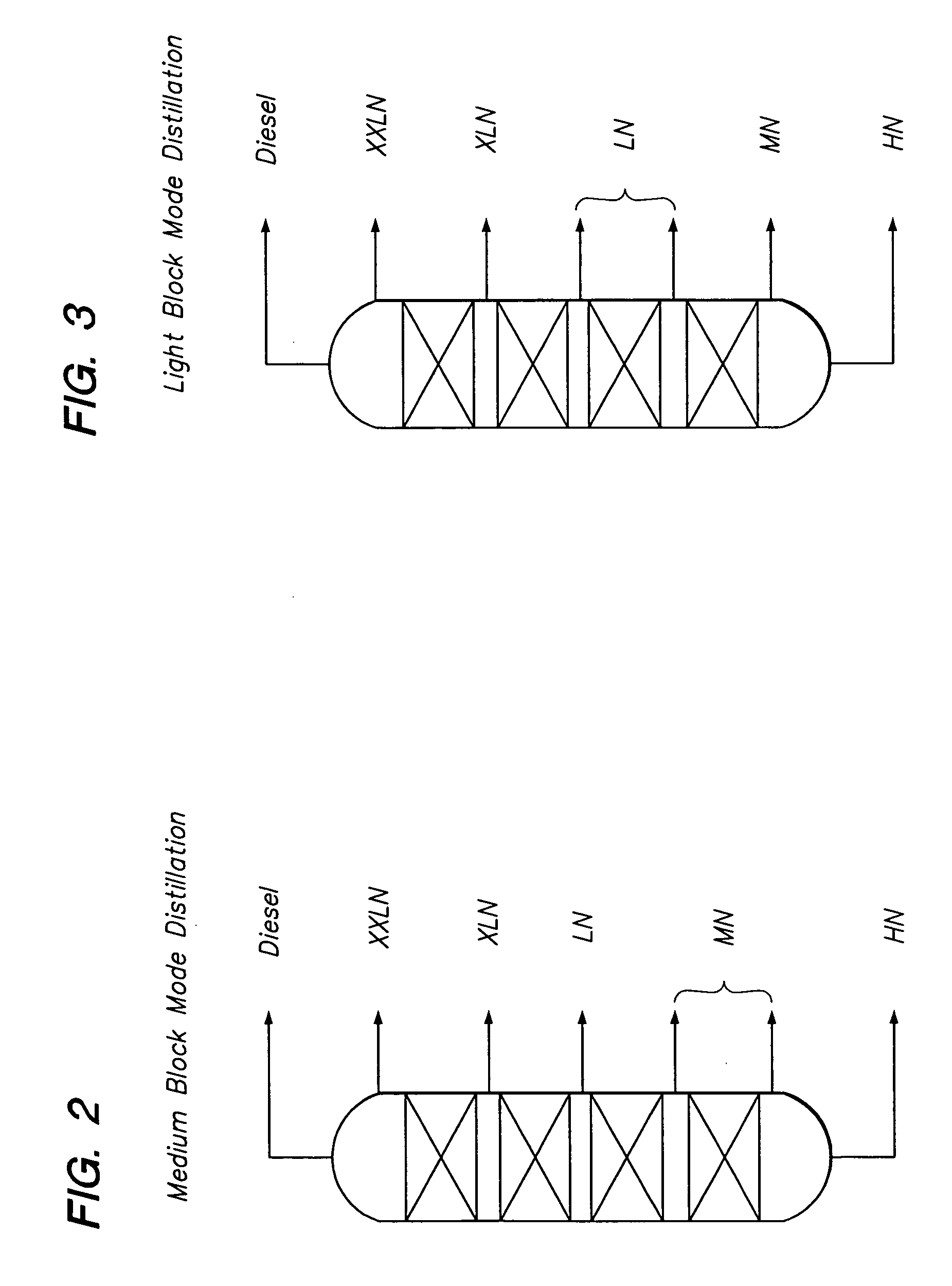
[0066] The distillation cut point ranges, product yields, and product properties produced by the two distillations are summarized below. Table 5 contains the data from the light block mode distillation, and Table 6 contains the data from the medium block mode distillation.

TABLE 5Light Block Mode Distillation with Six FractionsLight Block ModeL1L2L3L4L5L6Cut Point Range, ° F.550-650650-700700-753753-900900-10501050+   Distillation Yield, Wt. %18.3914.3015.4830.6815.06 6.09Gravity, °API47.644.643.241.640.036.2 Pour Point, ° C.−49−33−27−24−20−2  Viscosity at 100° C., cSt1.5912.3172.9044.3767.95521.62Viscosity Index—121129144157158   Noack Volatility, Wt. ...


PUM

PropertyMeasurementUnit
boiling pointaaaaaaaaaa
kinematic viscositiesaaaaaaaaaa

Abstract

A process for producing a product slate, which includes at least three base oil grades having kinematic viscosities at 100° C. within the range between about 1.8 cSt and 30 cSt, from a waxy feed having an initial boiling point of about 340° C. or less and a final boiling point of about 560° C. or higher, said process comprising (a) isomerizing at least a portion of the waxy feed, whereby the amount of isoparaffins present are increased; (b) distilling a first portion of the isomerized waxy feed in light block mode operation into at least three base oil fractions having different boiling ranges; (c) distilling a second portion of the isomerized waxy feed in medium block mode operation into at least three base oil fractions having different boiling ranges; and (d) blending at least one base oil fraction produced from light block mode with at least one base oil fraction produced from medium block mode to produce a lubricating base oil blend meeting a target value for at least one pre-selected property.

Description

FIELD OF THE INVENTION [0001] The present invention relates to a process scheme for the production of base oil blends prepared from a waxy feed using at least three side draws from the vacuum distillation tower which is operated alternately in light block mode and in medium block mode. BACKGROUND OF THE INVENTION [0002] Finished lubricants used for automobiles, diesel engines, axles, transmissions, and industrial applications consist of two general components, a base oil and one or more additives. Base oil is the major constituent in these finished lubricants and contributes significantly to the properties of the finished lubricant. In general, a few base oils are used to manufacture a wide variety of finished lubricants by varying the mixtures of individual base oils and individual additives. [0003] Although lubricating base oils traditionally have been prepared from conventional petroleum feedstocks, recent studies have shown that high quality lubricating base oils can be prepared...

Claims


Application Information

Patent Timeline
Patent Type & Authority Applications(United States)
IPC IPC(8): C10G71/00C10G73/02
CPCC10G7/003C10G2400/10C10G2300/1022C10G2300/301C10G2300/302C10G2300/304C10G2400/04Y10S208/95C10G45/58C10G71/00C10G73/02C10G73/42
Inventor ROSENBAUM, JOHN M.LOK, BRENT K.QUINNETT, PHILIP E.SIMMONS, CHRISTOPHER ALLEN
Owner CHEVROU USA INC
Why Eureka
Try Eureka