Method and device for mixing fluid flows

a fluid flow and fluid flow technology, applied in the direction of gas-gas reaction process, combustion using catalytic materials, combustion types, etc., can solve the problems of increased levels of undesirable nosub>x /sub>forming, lack of uniformity in the combustion process, and gas flow not having a defined outflow direction, etc., to achieve better mixing

Inactive Publication Date: 2006-09-14
ANSALDO ENERGIA SWITZERLAND AG
View PDF13 Cites 38 Cited by
  • Summary
  • Abstract
  • Description
  • Claims
  • Application Information

AI Technical Summary

Benefits of technology

[0006] The present invention is based on the general idea of effecting mixing with the aid of a plurality of opposite swirl flows which are arranged helically or annularly and concentrically with respect to an axial longitudinal center line extending in the main direction of flow. The formation of the largest possible number of swirl flows which rotate in opposite directions and are arranged concentrically inside one another leads to the formation of a correspondingly large number of concentric and likewise annular shearing layers, which effect intimate fluid mixing. The quality of mixing which can be achieve

Problems solved by technology

Inadequate mixing may lead to a lack of uniformity in the combustion process, in which relatively extensive temperature differences may be determined, with increased levels of undesirable NOx forming in zones which are at particularly high temperatures.
This means

Method used


Image

  • Method and device for mixing fluid flows
  • Method and device for mixing fluid flows
  • Method and device for mixing fluid flows

Examples


Embodiment Construction

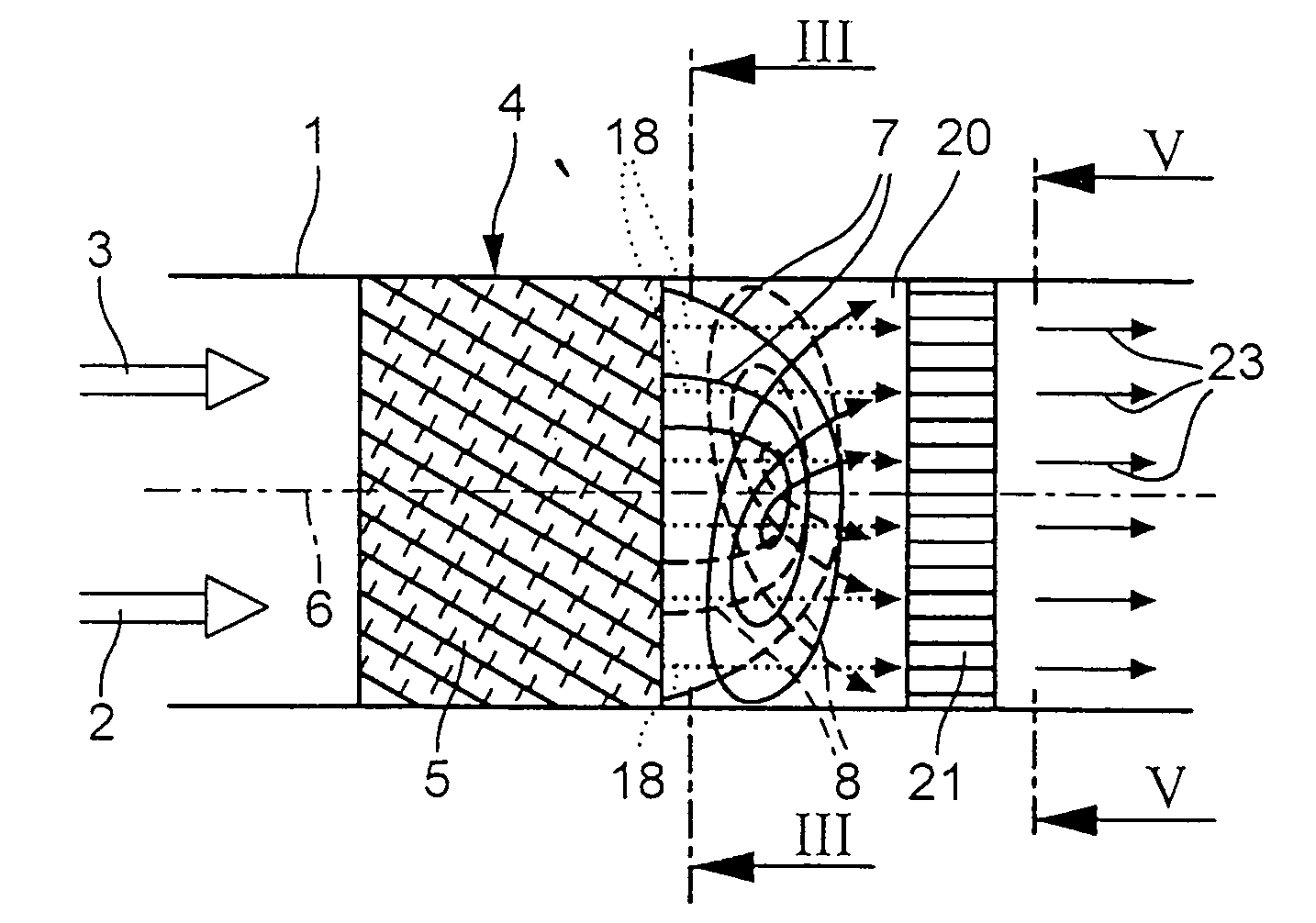
[0018]FIG. 1 shows a portion of a channel 1 into which at least two separate fluid flows 2 and 3 are introduced. It is preferable for the channel portion 1 to lead to a burner (not shown here) or to a combustor for heating a gas turbine of a power plant. The fluid flows are then preferably a fuel flow 2 and an oxidant flow 3, the fuel used preferably being natural gas and the oxidant used expediently being air.

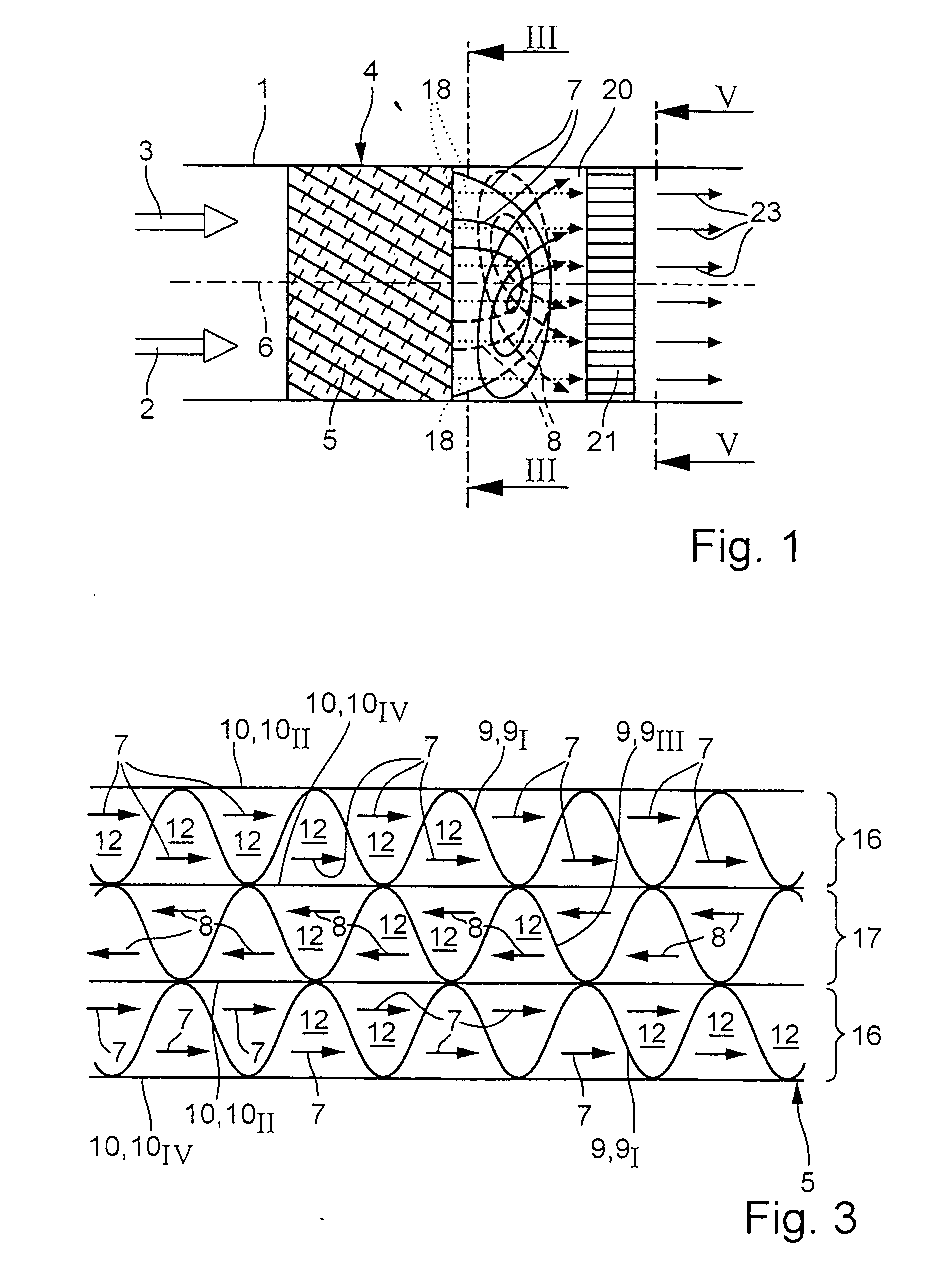
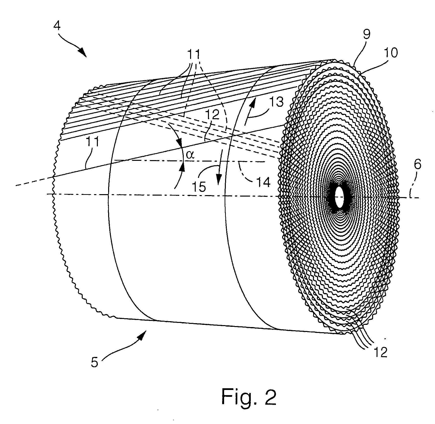
[0019] To achieve intensive mixing of the two fluid flows 2, 3, a device 4 according to the invention is arranged in the channel portion 1. The device 4 comprises a swirl generating structure 5, which is designed in such a way that when medium flows through it a plurality of annular swirl flows 7, 8 which are arranged concentrically with respect to an axial longitudinal center line 6, are generated, in such a manner that radially adjacent swirl flows 7, 8 each have an opposite direction of rotation. Therefore, to illustrate this, in FIG. 1 the first swirl flows 7 are illustra...


PUM

PropertyMeasurementUnit
Timeaaaaaaaaaa
Flow rateaaaaaaaaaa
Areaaaaaaaaaaa

Abstract

The present invention relates to a method for mixing at least two separate fluid flows (2, 3), in particular for a burner of a power plant. To improve the mixing, a plurality of swirl flows (7, 8), which are annular and concentric with respect to a longitudinal center line (6), are generated from the fluid flows (2, 3), in such a manner that radially adjacent swirl flows (7, 8) have opposite directions of rotation.

Description

FIELD OF THE INVENTION [0001] The present invention relates to a method and a device for mixing at least two separate fluid flows, in particular for a burner of a power plant. [0002] A range of applications require thorough mixing of separate gas flows. One such application is, for example, catalytic combustion for generating hot gas for operation of a gas turbine, in which a gaseous fuel, generally natural gas, and a gaseous oxidant, generally air, have to be intensively mixed before this fuel-oxidant mixture enters the respective catalyst. Conventional lean-mix premix burners also require the fuel-oxidant mixture supplied to be mixed as homogeneously as possible. Inadequate mixing may lead to a lack of uniformity in the combustion process, in which relatively extensive temperature differences may be determined, with increased levels of undesirable NOx forming in zones which are at particularly high temperatures. [0003] U.S. Pat. No. 5,202,203 and U.S. Pat. No. 5,328,359 show catal...

Claims


Application Information

Patent Timeline
IPC IPC(8): B05B7/10B01F5/06B01J12/00B01J19/24B01J19/32B01J35/04F23C13/00F23D14/62F23R3/40
CPCB01F3/02B01F5/0641B01F5/0643B01J12/007B01J19/2485B01J19/249B01J19/32B01J35/04B01J2208/00849B01J2219/2454B01J2219/2458B01J2219/2459B01J2219/2474B01J2219/2479B01J2219/2482B01J2219/2493B01J2219/3221B01J2219/32213B01J2219/32296B01J2219/33F23C13/00F23C13/02F23C13/06F23C99/00F23D14/62F23R3/286F23R3/40B01F23/10B01F25/4321B01F25/4322
Inventor CARRONI, RICHARDGRIFFIN, TIMOTHY
Owner ANSALDO ENERGIA SWITZERLAND AG
Why Eureka
Try Eureka