LED

a technology of led and led lenses, applied in the field of led, can solve the problems of inability to correct light emission properties well, inability to achieve good beam collimation, and increased errors when individual lenses are used, and achieves the effect of simple manner, low loss, and good correction of light emission properties

Inactive Publication Date: 2006-09-14
NANOGATE ADVANCED MATERIALS
View PDF5 Cites 4 Cited by
  • Summary
  • Abstract
  • Description
  • Claims
  • Application Information

AI Technical Summary

Benefits of technology

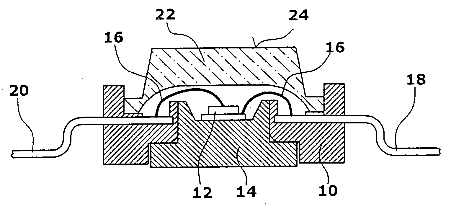
[0005] The LED of the present invention comprises a base body carrying the light generating element, such as a LED chip. A light guide body is arranged in the emitting direction of the light generating element. According to the invention, the light guide body comprises diffractive light guide elements. Providing light guide elements diffracting light has the advantage that an emission angle of the LED can be set in a simple manner with little loss. With the provision of diffractive light guide elements, as suggested by the invention, the light emission properties can be corrected well. In particular, it is possible to realize a good beam collimation. Since, in contrast to refractive elements, diffractive light guide elements have no marginal aberrations, a miniaturization of the individual diffractive light guide elements, as provided by the invention, is possible with good light emission properties.
[0016] In particular, a spectral splitting is avoided or substantially reduced, due to the present configuration of the display surface with diffractive surface elements. Further, a sufficient light amplification is ensured, while the energy consumption is low.
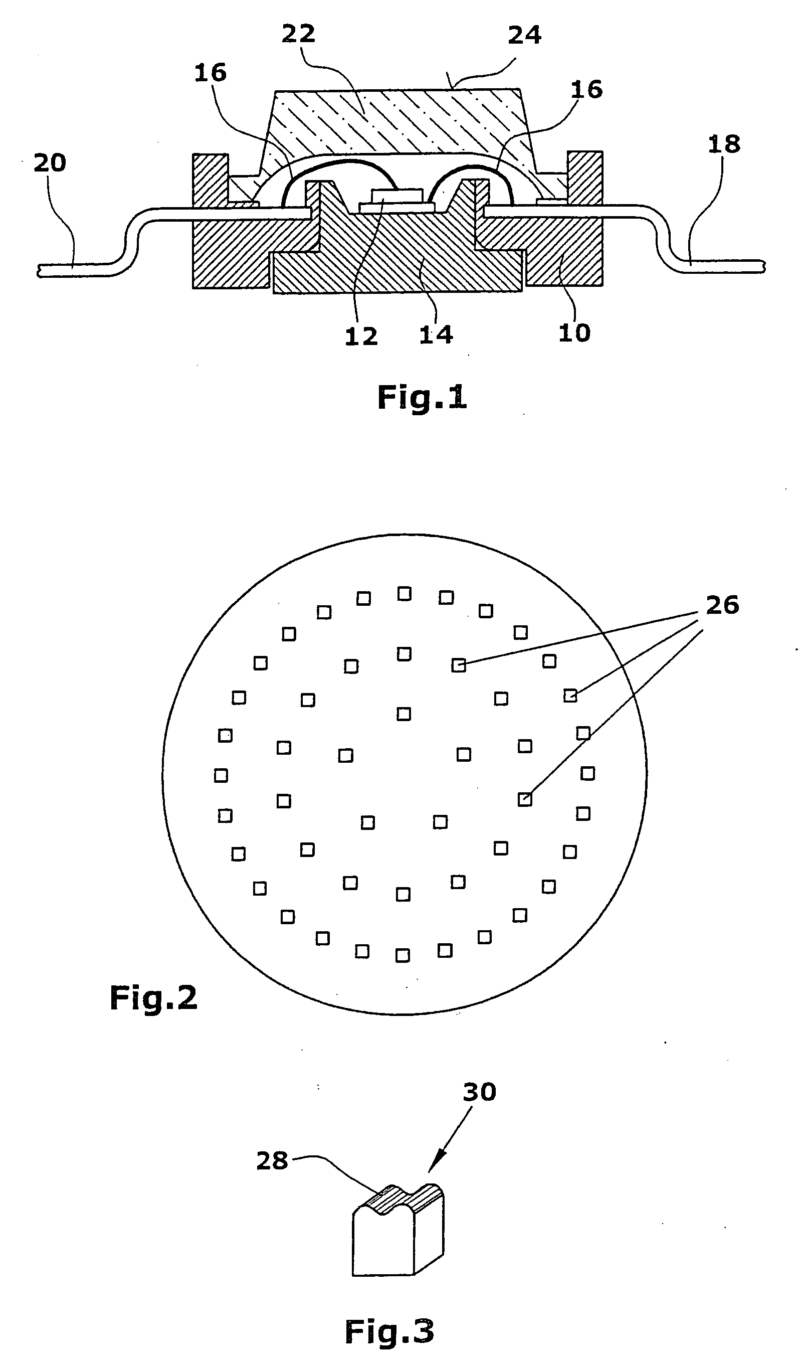
[0017] The present diffractive light guide elements preferably have a size of 0.04 μm2 to 10,000 μm2, in particular 0.04 μm2 to 500 μm2. Because such small surfaces are provided, it is possible to provide a plurality of surface elements even in very small flat screens such as displays for mobile applications. Here, the distance between individual light guide elements preferably lies in the range from 0 to 100 μm, in particular from 0 to 50 μm, and, most preferred, from 0 to 15 μm. It is particularly preferred that the light guide elements have a mutual distance >0. Preferably, the distance is at least 1 μm, in particular at least 3 μm. This has the advantage that the distance between the light guide elements can be decreased in areas, where more light is to be coupled out, whereas in areas, where a smaller amount of light is to be coupled out, larger distance can be provided. Thereby, a good uniformity of the distribution of luminosity can be achieved. Further, it is simpler in production to always arrange the individual light guide elements with a mutual distance. When the light guide elements are produced, for example, using a curing lacquer in combination with a forming element or a negative, spacing the light guide elements avoids corruption at the borders of the surface elements caused, e.g., by the occurrence of lacquer webs. Moreover, spacing the individual light guide elements ensures that refractions or corruptions of the diffraction caused by adjoining surface structures are avoided.
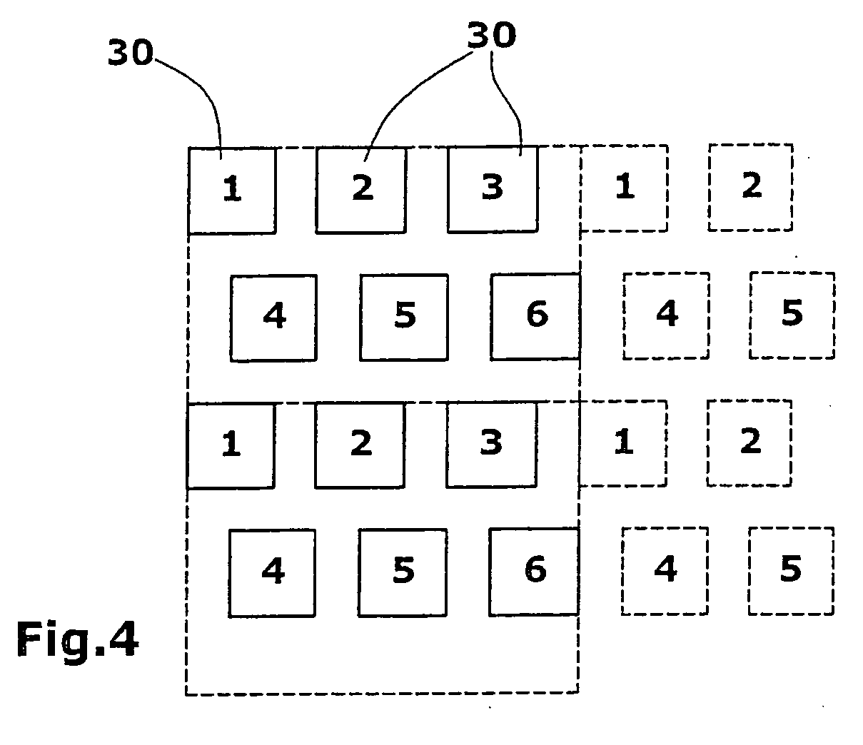
[0019] It is particularly preferred to configure the individual light guide elements such that the amplitude of the different surface structures is constant and only the frequency is changed. Depending on the type of surface structure, which does not necessarily have to be a sinusoidal surface structure, all raised portions, generally speaking, have the same height, yet have different mutual distances. This results in the fact that light emitted from the light source is diffracted differently by the individual surface elements. In this context, it is particularly advantageous that varying distances are simpler to produce than varying heights.
[0023] It is particularly preferred to configure the individual light guide elements such that the amplitude of the different surface structures is constant and only the frequency is changed. Depending on the type of surface structure, which does not necessarily have to be a sinusoidal surface structure, all raised portions, generally speaking, have the same height, yet have different mutual distances. This results in the fact that light emitted from the light source is diffracted differently by the individual light guide elements. In this context, it is particularly advantageous that varying distances are simpler to produce than varying heights.

Problems solved by technology

The refraction of the light emitted by the light generating element caused by refractive light guide elements results in that the light emission properties can not well be corrected.
In particular, no good beam collimation is possible.
Since refractive elements are lenses, in particular, which always show marginal aberrations, the errors increase when the individual lenses are miniaturized, since a plurality of small lenses has more margins than one large lens.

Method used


Image

  • LED
  • LED
  • LED

Examples


Embodiment Construction

[0031] An LED comprises a base body 10 that carries a light generating element 12, such as a LED chip. Possibly, the base body additionally comprises a heat conductor body 14 for cooling the light generating element 12. Lines 16 connect the light generating element 12 with a cathode 18 and an anode 20 in the emitting direction, i.e. upward in FIG. 1, a light guide body 22 is provided. The light guide body 22 is fastened to the base body 10. Groups of diffractive light guide elements 26 (FIG. 2) are arranged on a top surface 24 of the light guide body 22.

[0032] The groups of diffractive light guide elements 26 provided according to the invention, which may be arranged in concentric circles on the surface 24, serve to determine the emission angle of a LED. Using correspondingly configured and arranged light guide elements, small emission angles can be realized.

[0033] The individual groups of light guide elements 26 comprise a plurality of light guide elements 30. In an embodiment il...


PUM


Abstract

A LED comprises a base body. The base body carries a light generating element. A light guide body is provided in the emitting direction of the light generating element. According to the invention, the light guide body comprises diffractive groups of light guide elements to fix the emission angle of the LED.

Description

CROSS REFERENCE TO RELATED APPLICATIONS [0001] This application claims priority to European patent application No. 05 005 252.1 filed on Mar. 10, 2005, and to U.S. provisional patent application No. 60 / 691,707 filed Jun. 17, 2005, which applications are hereby incorporated by this reference in their entireties.BACKGROUND OF THE INVENTION [0002] The invention refers to a LED. [0003] LED's, i.e. light emitting diodes, are used in a variety of devices and find widespread use today. Depending on the materials used, an LED generates light in different colors, both in the visible and the non-visible range. A light guide body is associated to this light generating element in the emitting direction. The emission angle of the LED is determined by the light guide body which is most often made of plastic material. Known light guide bodys are refractive elements such as lenses, for example. The refraction of the light emitted by the light generating element caused by refractive light guide elem...

Claims


Application Information

Patent Timeline
Patent Type & Authority Applications(United States)
IPC IPC(8): H01L33/00H01L33/58
CPCH01L33/58
Inventor KLENKE, MARTIN
Owner NANOGATE ADVANCED MATERIALS
Why Eureka
Try Eureka