Inspection of non-planar parts using multifrequency eddy current with phase analysis

a non-planar part and phase analysis technology, applied in the direction of mechanical measuring arrangements, mechanical roughness/irregularity measurements, instruments, etc., can solve problems such as interference with crack detection, and achieve the effect of easy detection and visualization, and increasing the signal-to-noise ratio

a non-planar part and phase analysis technology, applied in the direction of mechanical measuring arrangements, mechanical roughness/irregularity measurements, instruments, etc., can solve problems such as interference with crack detection, and achieve the effect of easy detection and visualization, and increasing the signal-to-noise ratio

US20060202687A1Inactive Publication Date: 2006-09-14GENERAL ELECTRIC CO

Image

  • Inspection of non-planar parts using multifrequency eddy current with phase analysis
  • Inspection of non-planar parts using multifrequency eddy current with phase analysis
  • Inspection of non-planar parts using multifrequency eddy current with phase analysis

Examples


Embodiment Construction

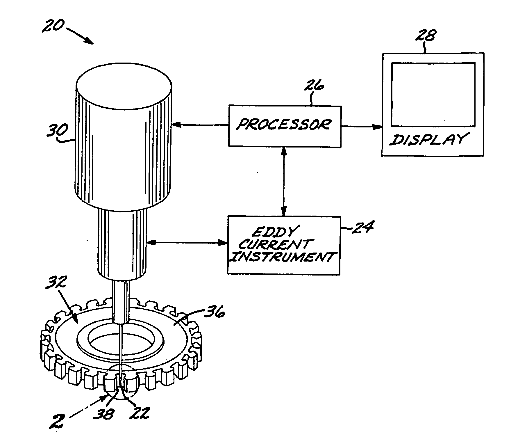
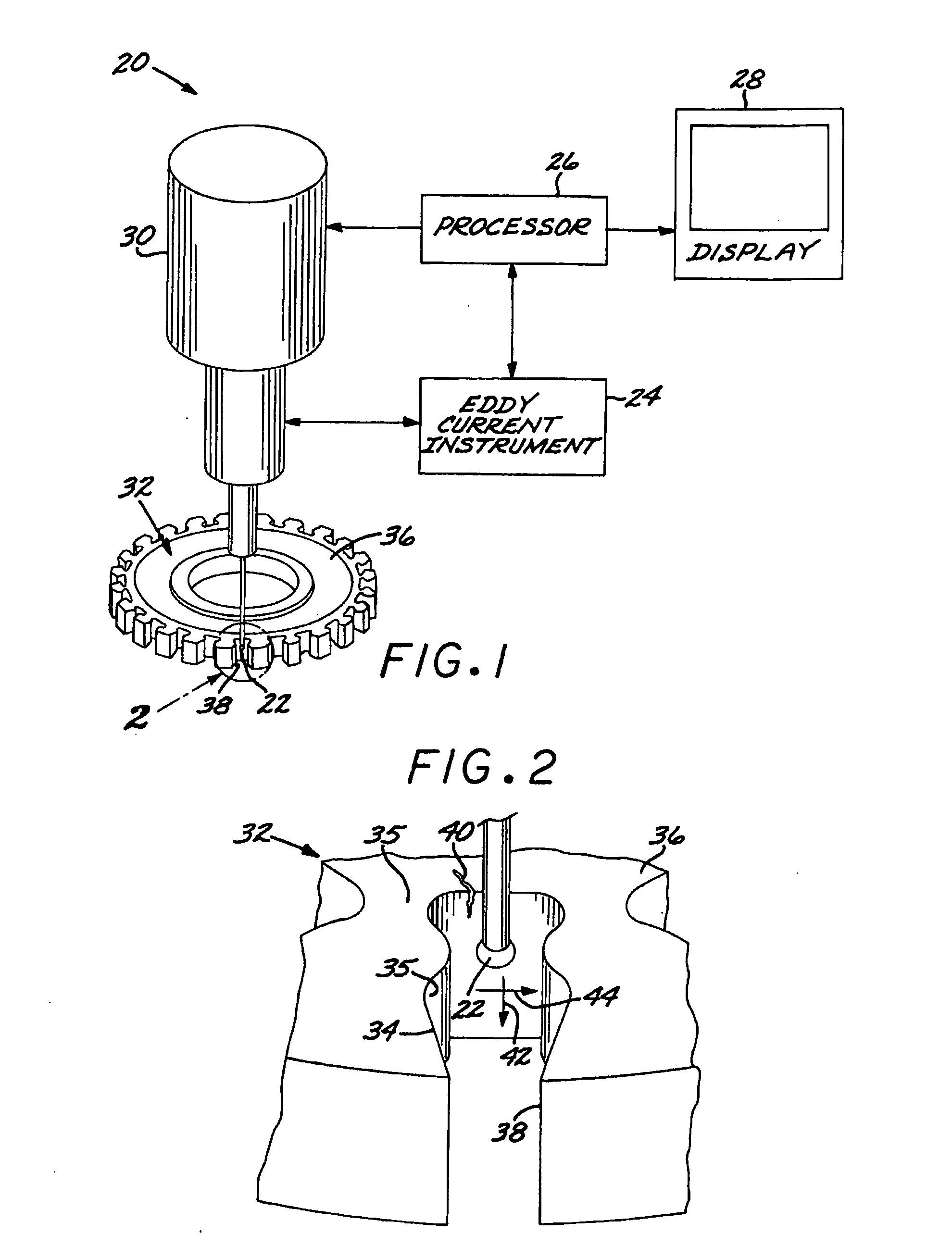
[0025]FIG. 1 depicts an exemplary inspection system 20 for performing the inspection of non-planar parts. As used herein, a “part” includes any object being inspected by the present approach, including but not limited to articles, components, structures, test specimens, and the like. A “non-planar part” is such an object wherein the surface of the region of the part being inspected is not planar. That is, it has an edge, a contour, or other non-planar surface feature.

[0026] The inspection system 20 includes an eddy current probe 22, an eddy current instrument 24, a processor 26, and a display 28, all interconnected by appropriate cabling. The physical configuration of such inspection systems 20 is known in the art, except for the improvements discussed herein. The eddy current probe 22 is configured to induce eddy currents in a non-planar part 32 and to measure the resulting eddy current response signals, in order to inspect the non-planar part 32. Such eddy current probes are know...


PUM

PropertyMeasurementUnit
eddy current techniqueaaaaaaaaaa
frequenciesaaaaaaaaaa
frequencyaaaaaaaaaa

Abstract

A non-planar part has a non-planar surface such as an edge, and may contain an anomaly such as a crack. The non-planar part is inspected using an eddy current technique. The method includes providing the non-planar part having the non-planar surface thereon, driving an eddy current probe at two or more frequencies, measuring an eddy current response signal of the non-planar part at each frequency, and performing a multifrequency phase analysis on the eddy current response signals.

Description

[0001] This application is a continuation-in-part of parent application Ser. No. 11 / 210,119, filed Aug. 22, 2005, for which priority is claimed and whose disclosure is incorporated herein by reference, and through the parent application further claims the benefit of U.S. Provisional Application No. 60 / 660,032, filed Mar. 9, 2005, the disclosure of which is hereby incorporated herein by reference.[0002] This invention relates to the inspection of a part by the eddy current technique and, more particularly, to the multifrequency eddy current inspection of a non-planar part with phase analysis of the multifrequency eddy current signal. BACKGROUND OF THE INVENTION [0003] A number of non-destructive inspection techniques are in widespread use. These non-destructive inspection techniques allow a part to be inspected for anomalies without sectioning or etching the part, and without otherwise altering the structure of the part, which procedures in themselves add further anomalies to the par...

Claims


Application Information

Patent Timeline
14 Sep 2006
Publication
US20060202687A1
IPC
G01N27/82
CPC
G01N27/9046; G01N27/9086
Inventors
WANG, CHANGTING; SUH, UI