Antenna unit

a technology of antenna unit and conductor, which is applied in the direction of antenna details, non-resonant long antennas, antennas, etc., can solve the problem of actually quite difficult to wind the plurality of conductors around the cylindrical member in helical fashion, and achieve the effect of preventing water invasion

Inactive Publication Date: 2006-09-14
MITSUMI ELECTRIC CO LTD
View PDF4 Cites 8 Cited by
  • Summary
  • Abstract
  • Description
  • Claims
  • Application Information

AI Technical Summary

Benefits of technology

[0015] It is therefore an object of this invention to provide a pole-type antenna unit capable of fixing a board and preventing water invasion from a cable side.

Problems solved by technology

On the other hand, it is actually quite difficult to wind the plurality of conductors around the cylindrical member in the helical fashion.

Method used


Image

  • Antenna unit
  • Antenna unit
  • Antenna unit

Examples


Embodiment Construction

[0037] Now, an embodiment of this invention will be described in detail with reference to the drawings.

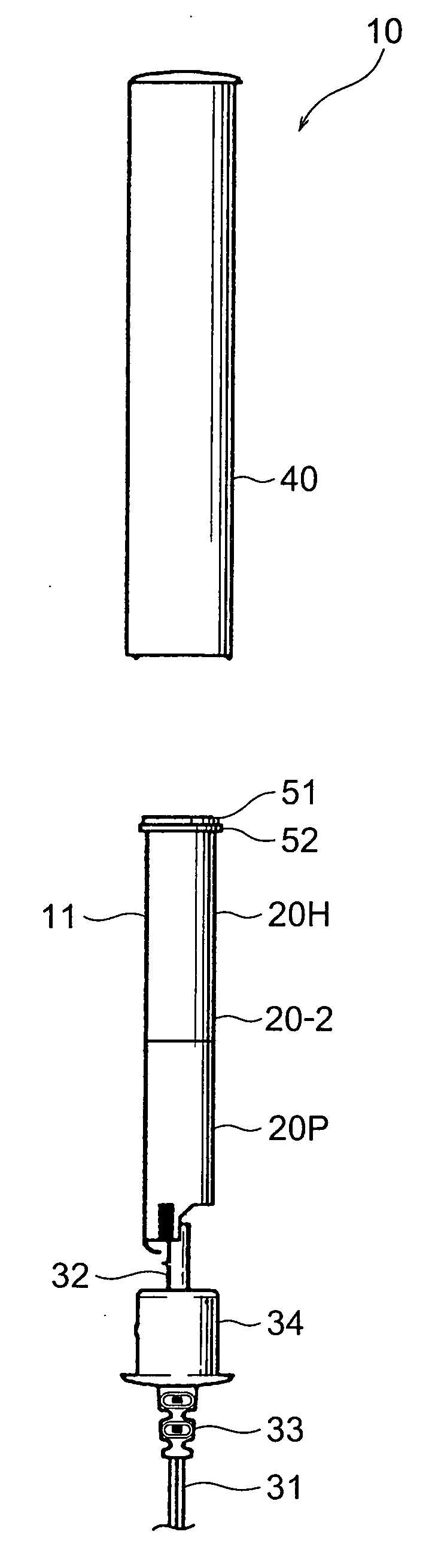
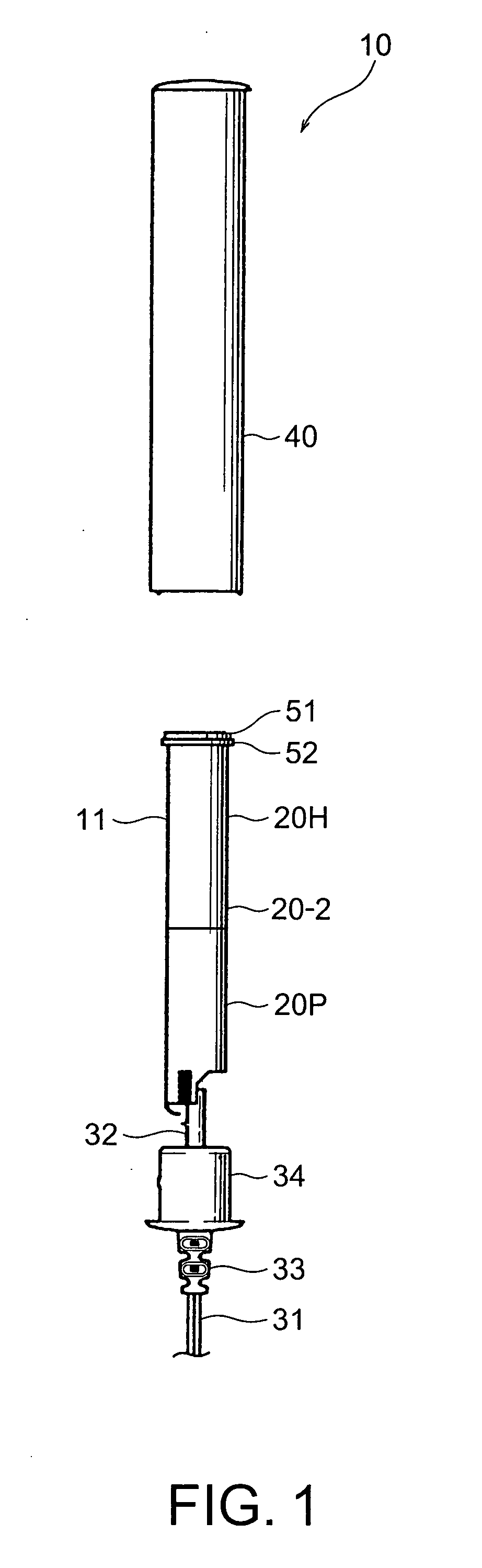
[0038] Referring to FIG. 1 and FIGS. 2A and 2B, description will be made about a pole-type antenna unit 10 according to the embodiment of this invention. The pole-type antenna unit 10 is an antenna unit for a digital radio receiver and is connected to a digital radio tuner (not shown) incorporated in a housing of a portable electronic device (not shown) through a cable 31 and a connector (not shown) so as to be used.

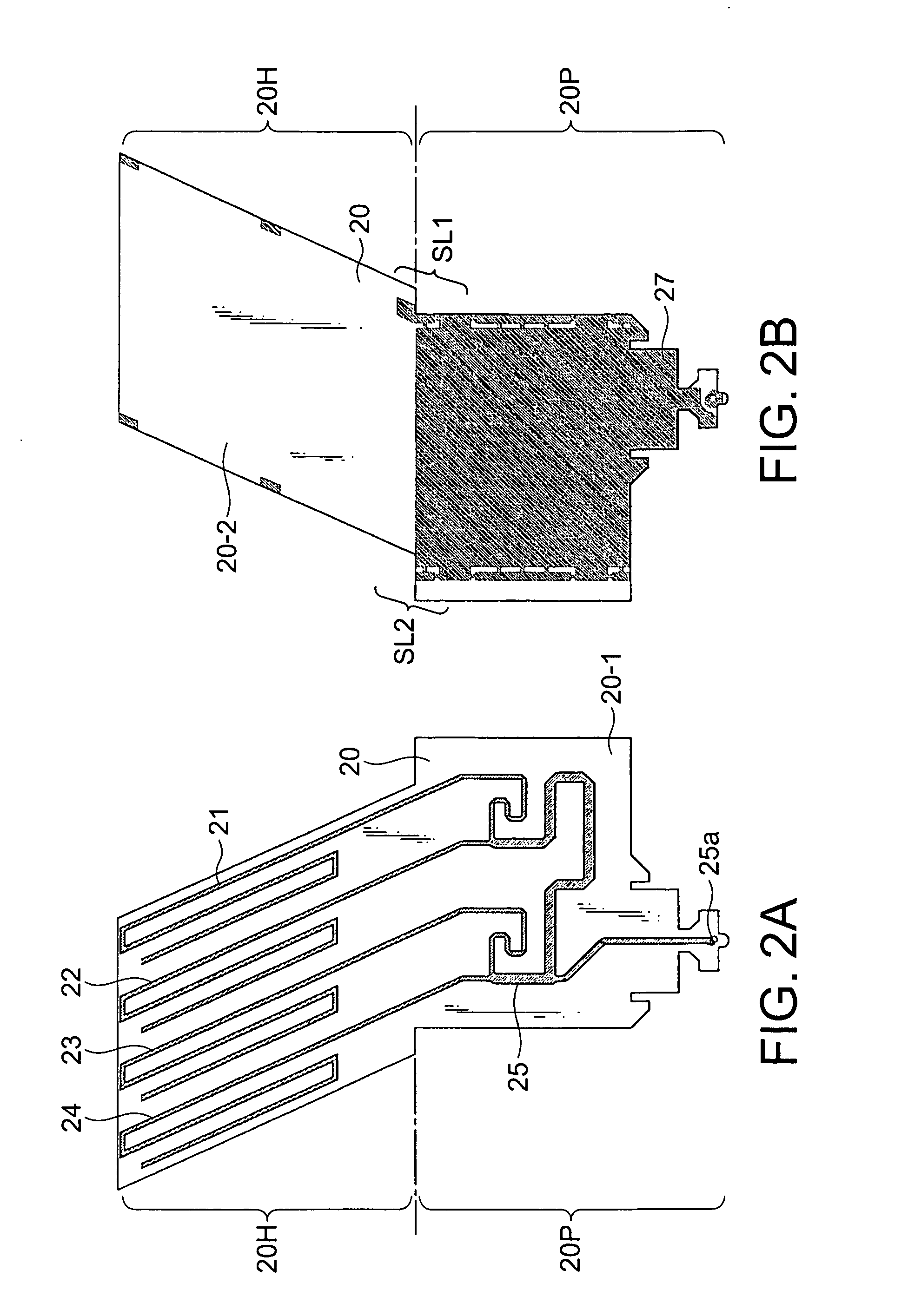
[0039] The pole-type antenna unit 10 comprises a hollow cylindrical member 11 formed by rolling a flexible insulating film member 20 as shown in FIGS. 2A and 2B into a hollow cylinder. FIG. 2A shows a first surface 20-1 of the insulating film member 20 while FIG. 2B shows a second surface 20-2 of the insulating film member 20. The insulating film member 20 is composed of a helical antenna portion 20H and a phase shifter portion 20P. The helical antenna portion 20H has...


PUM


Abstract

An antenna unit comprises a hollow cylindrical member obtained by forming a flexible insulating film member into a hollow cylinder, an antenna pattern composed of at least one conductor formed at the hollow cylindrical member, and a board mounted with a low-noise amplifier. A hollow cylindrical cover case covers the hollow cylindrical member and the board. A cable having one end is connected to the low-noise amplifier and extends downward from a lower end of the cover case. The antenna unit further comprises an undercap attached to the lower end of the cover case and a packing press-fitted into the undercap. The board is inserted in the packing.

Description

[0001] This application claims priority to prior Japanese patent application JP 2005-66652, the disclosure of which is incorporated herein by reference. BACKGROUND OF THE INVENTION [0002] This invention relates to a pole-type antenna unit and, in particular, to a pole-type and personal-type miniature antenna unit for a digital radio receiver for receiving an electric wave from an artificial satellite (that may be called a “satellite wave”) or an electric wave on the ground (that may be called a “terrestrial wave”) to listen in a digital radio broadcasting. [0003] In recent years, a digital radio receiver, which receives the satellite wave or the terrestrial wave to listen the digital radio broadcasting, has been developed and is put to practical use in the United States of America. The digital radio receiver is generally mounted on a mobile station, such as an automobile, and can receive an electric wave having a frequency of about 2.3 gigahertz (GHz) to listen in a radio broadcasti...

Claims


Application Information

Patent Timeline
Patent Type & Authority Applications(United States)
IPC IPC(8): H01Q1/42
CPCH01Q1/242H01Q1/42H01Q11/08H01Q23/00
Inventor NORO, JUNICHIKATO, TAKAO
Owner MITSUMI ELECTRIC CO LTD
Why Eureka
Try Eureka