Image display device and projector

a technology which is applied in the field of image display device and projector, can solve the problems of not fully exerting the expression capability inherent in cg contents, the display device to display hdr display data, and the viewer is not completely satisfied with the display image in terms of reality and visual impact, so as to enhance the contrast characteristic of the optical image of the first light modulation element, the effect of sharp imag

Inactive Publication Date: 2006-09-14
138 EAST LCD ADVANCEMENTS LTD
View PDF11 Cites 20 Cited by
  • Summary
  • Abstract
  • Description
  • Claims
  • Application Information

AI Technical Summary

Benefits of technology

[0013] An advantage of the invention is to provide an image display device and a projector capable of obtaining a sharp image by enhancing the contrast characteristic.
[0014] The advantage can be achieved by the configurations as follows.
[0015] A first aspect of the invention provides an image display device that displays an image by modulating a light from a light source according to display image data. The image display device includes a first light modulation element that modulates a light emitted from the light source, and a second light modulation element that is disposed on an optical path in series with the first light modulation element and modulates a light exiting from the first light modulation element. The first light modulation element and the second light modulation element are disposed in such a manner that a bright-field direction of an optical image of the first light modulation element and a bright-field direction of the second light modulation element almost coincide with each other.
[0016] According to the first aspect of the invention, a light emitted from the light source is modulated by the first light modulation element first, and then modulated by the second light modulation element. In this instance, because the bright-field direction of the optical image of the first light modulation element and the bright-field direction of the second light modulation direction almost coincide with each other, the contrast characteristic of the optical image of the first light modulation element can be enhanced to the maximum. The homogeneity and the contrast characteristic of an image exiting from the second light modulation element are therefore enhanced, which enables a sharp image to be obtained.
[0017] It is preferable that the image forming device further includes an image forming system that forms the optical image of the first light modulation element on a light-receiving surface of the second light modulation element.
[0018] Brightness, chromaticity, contrast, etc. can be made uniform in a reliable manner by providing the image forming system, and the image display quaintly can be satisfactorily. It is preferable that the image forming system is an inverted image forming portion, and that the bright-field direction of the optical image of the first light modulation element and the bright-field direction of the second light modulation element almost coincide with each other while the first light modulation element and the second light modulation element are disposed to be rotational symmetric by 180° about an optical axis.

Problems solved by technology

In addition, because gradation in a shadow portion and a highlight portion is insufficient, the viewer is not completely satisfied with a display image in terms of reality and a visual impact.
However, because the ability of a display device to display the HDR display data is inadequate, there is a problem that the expression capability inherent to CG contents is not fully exerted.
When the liquid crystal light valves are disposed inadequately, inhomogeneity, such as irregular brightness and irregular colors, results in a display image or the contrast characteristic is deteriorated.
This poses a problem that an image quality of the display image is deteriorated markedly.
This not only prevents an increase of the overall device in size, but also saves the cost because the components can be fewer.

Method used


Image

  • Image display device and projector
  • Image display device and projector
  • Image display device and projector

Examples


first embodiment

[0041] First Embodiment of Projector

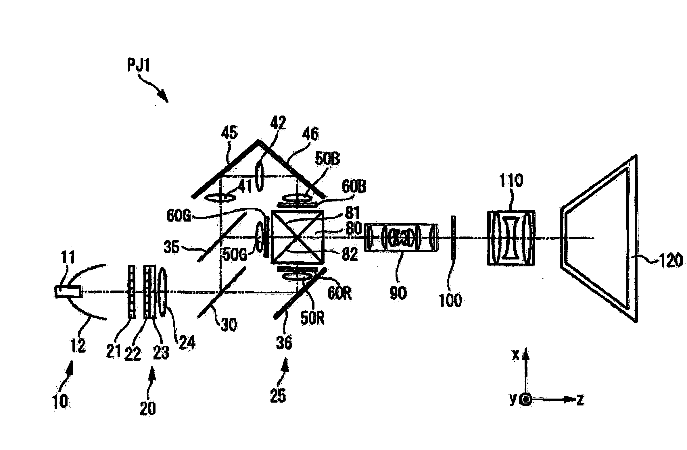
[0042]FIG. 1 is a view showing the major optical configuration of a projection type liquid crystal display device (projector) PJ1.

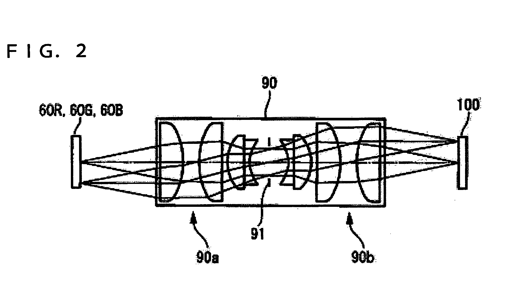
[0043] The projector PJ1 comprises an image display device including: a light source 10; a uniform illumination system 20 that makes a luminance distribution of a light coming incident thereon from the light source 10 uniform; a color modulation portion 25 that modulates luminance of three primary colors, RGB, among the wavelength regions of a light coming incident thereon from the uniform illumination system 20 (including three transmissive liquid crystal light valves as a first modulation element, that is, a transmissive liquid crystal light valve 60B for a blue light, a transmissive liquid crystal light valve 60G for a green light, and a transmissive liquid crystal light valve 60R for a red light); a relay lens 90 that relays a light coming incident thereon from the color modulation portion 25; and a transmissive li...


PUM


Abstract

An image display device that displays an image by modulating a light from a light source according to display image data, includes: a first light modulation element that modulates a light emitted from the light source; and a second light modulation element that is disposed on an optical path in series with the first light modulation element and modulates a light exiting from the first light modulation element, wherein the first light modulation element and the second light modulation element are disposed in such a manner that a bright-field direction of an optical image of the first light modulation element and a bright-field direction of the second light modulation element almost coincide with each other.

Description

BACKGROUND [0001] 1. Technical Field [0002] The present invention relates to a device that displays an image by modulating a light from a light source via plural light modulation elements, and more particularly, to an image display device and a projector suitable to achieve a wider luminance dynamic range and a greater number of gradation steps. [0003] 2. Related Art [0004] Improvements of an image quality in recent years with electronic display devices, such as an LCD (Liquid Crystal Display), an EL (Electro-luminescence) display, a plasma display, a CRT (Cathode Ray Tube), and a projector, are remarkable. A device with the ability comparable to the characteristics of human vision as to resolution and color gamut is now being achieved. However, the reproducible range of the luminance dynamic range is limited to a range of the order of 1 to 102 [nit], and the gradation steps is normally expressed by 8 bits. On the other hand, the luminance dynamic range perceivable by the human visi...

Claims


Application Information

Patent Timeline
Patent Type & Authority Applications(United States)
IPC IPC(8): G03B21/00
CPCH04N9/3126H04N9/3152H04N9/3197
Inventor UCHIYAMA, SHOICHINAKAMURA, JUNICHINITTA, TAKASHIASAHI, TSUNEMORI
Owner 138 EAST LCD ADVANCEMENTS LTD
Why Eureka
Try Eureka