
Chromatic dispersion and dispersion slope compensating apparatus

a slope compensating and chromatic dispersion technology, applied in the direction of optical elements, multiplex communication, instruments, etc., can solve the problems of requiring a complicated control mechanism, requiring enormous cost, and difficult design and manufacturing of such a adjusting mechanism, and achieves low cost and easy practical use.

Inactive Publication Date: 2006-09-14
FUJITSU LTD
View PDF9 Cites 15 Cited by
  • Summary
  • Abstract
  • Description
  • Claims
  • Application Information

AI Technical Summary

Benefits of technology

[0013] The present invention has been accomplished in view of the above problems and has an object to provide a low cost apparatus capable of variably compensating for the chromatic dispersion and the dispersion slope independent of each other, with a simple control mechanism.
[0016] According to the above chromatic dispersion and dispersion slope compensating apparatus of the present invention as described above, it is possible to variably compensate for the chromatic dispersion and the dispersion slope independent of each other, with the simple control mechanism which moves the plurality of three-dimensional mirrors of the reflecting section to the second direction. Thus, it becomes possible to provide the chromatic dispersion and dispersion slope compensating apparatus which is easy to be in practical use and is at a low cost.

Problems solved by technology

However, in the conventional chromatic dispersion and dispersion slope compensating apparatus utilizing the VIPA described above, there is a problem of requiring a complicated control mechanism.
But, the designing and the manufacturing of such an adjusting mechanism are not easy and an enormous cost is required.
Therefore, there has been a problem in that the conventional apparatus is actually hard to be in practical use.

Method used


Image

  • Chromatic dispersion and dispersion slope compensating apparatus
  • Chromatic dispersion and dispersion slope compensating apparatus
  • Chromatic dispersion and dispersion slope compensating apparatus

Examples


Embodiment Construction

[0034] Hereinafter, embodiments of the present invention will be described with reference to drawings. The same reference numerals denote the same or equivalent parts in all drawings.

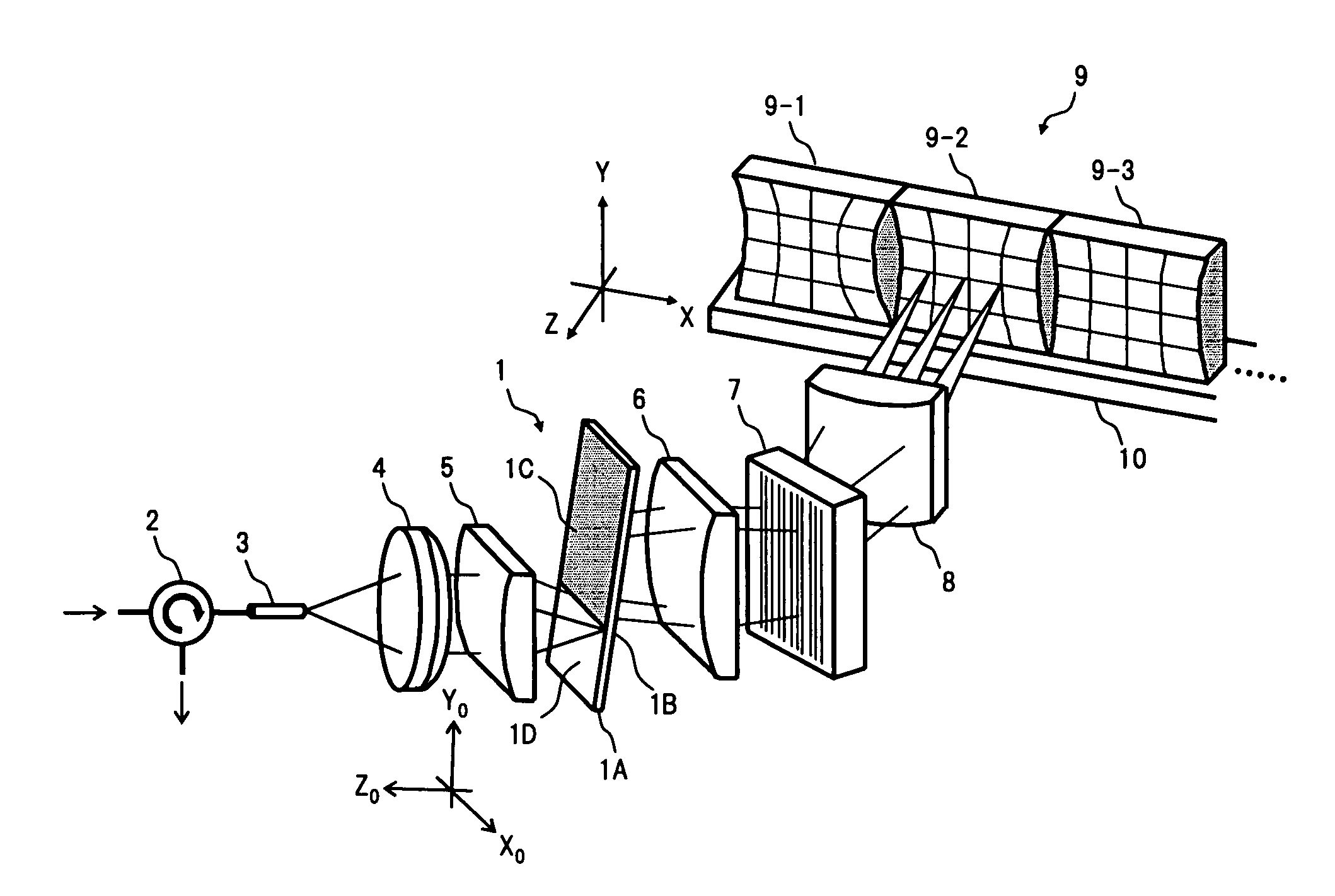
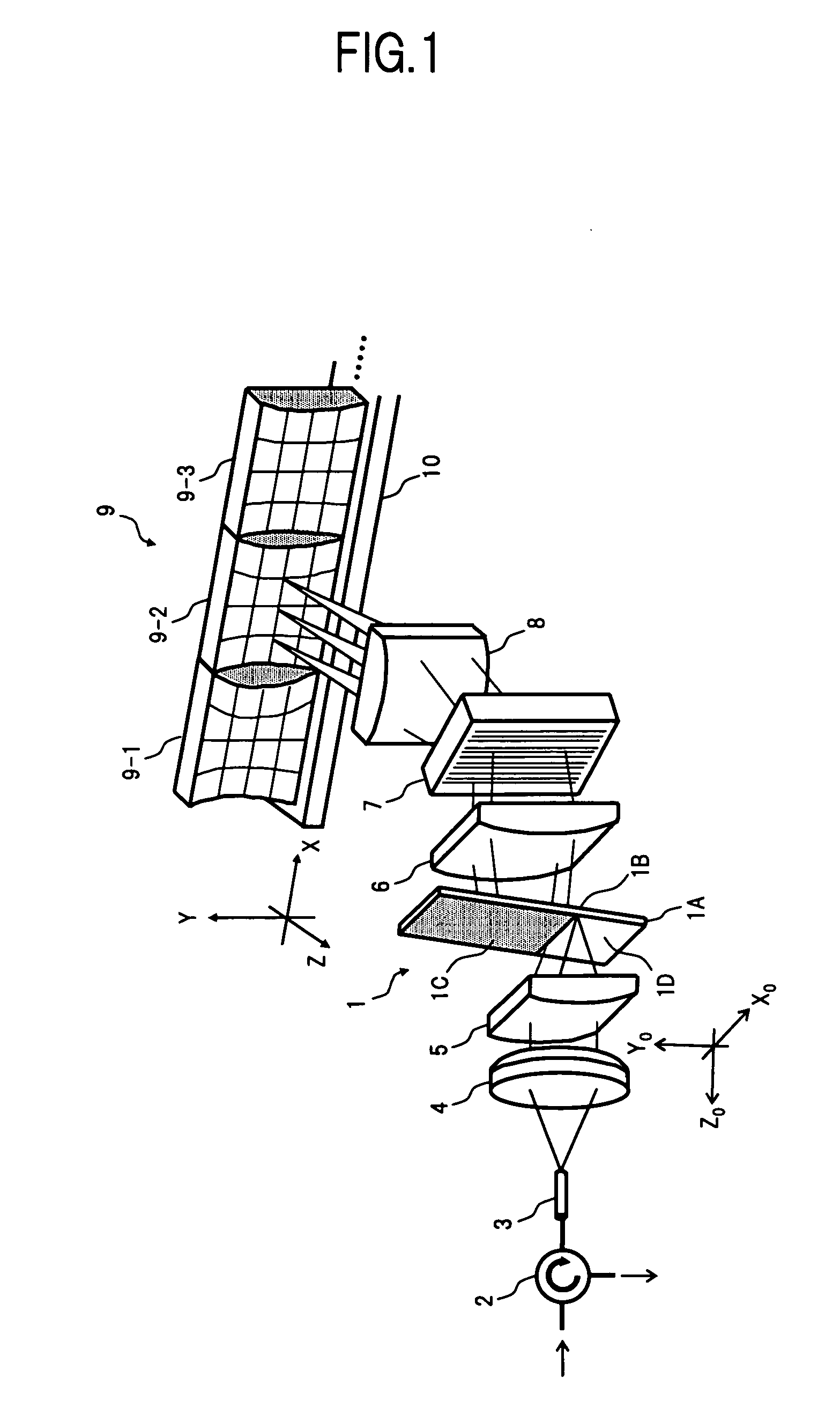
[0035]FIG. 1 is a perspective view showing a configuration of one embodiment of a chromatic dispersion and dispersion slope compensating apparatus according to the present invention. Further, FIG. 2 is a top view of the configuration in FIG. 1.

[0036] In FIG. 1, the apparatus in the present embodiment comprises, for example: a VIPA plate 1 as an optical component having two reflective surfaces which are opposed and parallel to each other; an optical system which consists of an optical circulator 2, an optical fiber 3, a collimate lens 4 and a cylindrical lens 5, enabling a WDM light condensed on one segment to be incident on a radiation window 1D of the VIPA plate 1; a cylindrical lens 6 (first lens), a diffraction grating 7 and a cylindrical lens 8 (second lens), which are sequentially given with a li...


PUM


Abstract

In a chromatic dispersion and dispersion slope compensating apparatus according to the present invention, a WDM light which has been angularly dispersed to a first direction by a VIPA plate, is angularly dispersed to a second direction vertical to the first direction by a diffraction grating, and optical signals of respective wavelengths output from the diffraction grating are reflected by any one of a plurality of three-dimensional mirrors having reflective surfaces of curved shapes different from each other, to be returned to the VIPA plate. Thus, with a simple control mechanism in which the plurality of three-dimensional mirrors are moved to only the second direction, an apparatus capable of variably compensating for the chromatic dispersion and the dispersion slope independent of each other can be provided.

Description

BACKGROUND OF THE INVENTION [0001] 1. Field of the Invention [0002] The present invention relates to an apparatus for compensating for the chromatic dispersion and the dispersion slope generated in optical signals of respective wavelengths which are contained in a wavelength division multiplexed light transmitted through an optical fiber transmission path, and in particular, to an apparatus capable of variably compensating for the chromatic dispersion and the dispersion slope independent of each other. [0003] 2. Description of the Related Art [0004] In an optical transmission system, it is necessary to perform the chromatic dispersion compensation, in order to suppress the wavelength deterioration which occurs due to a difference between optical fiber propagation times of respective wavelength components of modulated optical signals. As one of conventional chromatic dispersion compensators, there has been known, for example, a chromatic dispersion compensator configured by utilizing...

Claims


Application Information

Patent Timeline
Patent Type & Authority Applications(United States)
IPC IPC(8): H04J14/02G02B5/18G02B27/44G02B6/26G02B26/00
CPCG02B6/29311G02B6/29313G02B6/29358G02B6/29394H04B10/25133
Inventor MIURA, AKIRAOOI, HIROKIYAMAUCHI, YASUHIROKUBOTA, YOSHINOBU
Owner FUJITSU LTD
Learn More