Fireguard circuit

a safety device and circuit technology, applied in emergency protective arrangements, emergency protective arrangements for limiting excess voltage/current, electrical equipment, etc., can solve problems such as ground fault conditions, ground fault conditions, and potential dangers, and achieve the effect of convenient assembly

Inactive Publication Date: 2006-09-14
TOWER MFG
View PDF31 Cites 8 Cited by
  • Summary
  • Abstract
  • Description
  • Claims
  • Application Information

AI Technical Summary

Benefits of technology

[0014] It is yet another object of the present invention to provide a safety circuit as described above which may be mass produced, has a minimal number of parts, and can be easily assembled.

Problems solved by technology

The connection of an electrical appliance to a power supply through a pair of conducting lines can create a number of potentially dangerous conditions.
In particular, there exists the risk of ground fault and grounded neutral conditions in the conducting lines.
A ground fault condition occurs when there is an imbalance between the currents flowing in the power and neutral lines.
The second voltage is sufficient to maintain the solenoid in its energized state after being initially energized by the first voltage but is insufficient to switch the solenoid from its de-energized state to its energized state.
While GFCI circuits of the type described above are well known and widely used in commerce to protect against ground fault and grounded neutral conditions, it should be noted that a power cable is susceptible to other types of hazardous conditions which are not protected against by a conventional GFCI circuit.
It should be noted that the presence of this type of arcing condition between either the power line and the metal sheath or the neutral line and the metal sheath can result in a fire or other dangerous condition, which is highly undesirable.
Although well known in commerce, the GFCI disclosed in Legatti suffers from a notable drawback.
As can be appreciated, the implementation of a differential transformer significantly increases the overall size and cost of the product, which is highly undesirable.

Method used


Image

  • Fireguard circuit
  • Fireguard circuit
  • Fireguard circuit

Examples


first embodiment

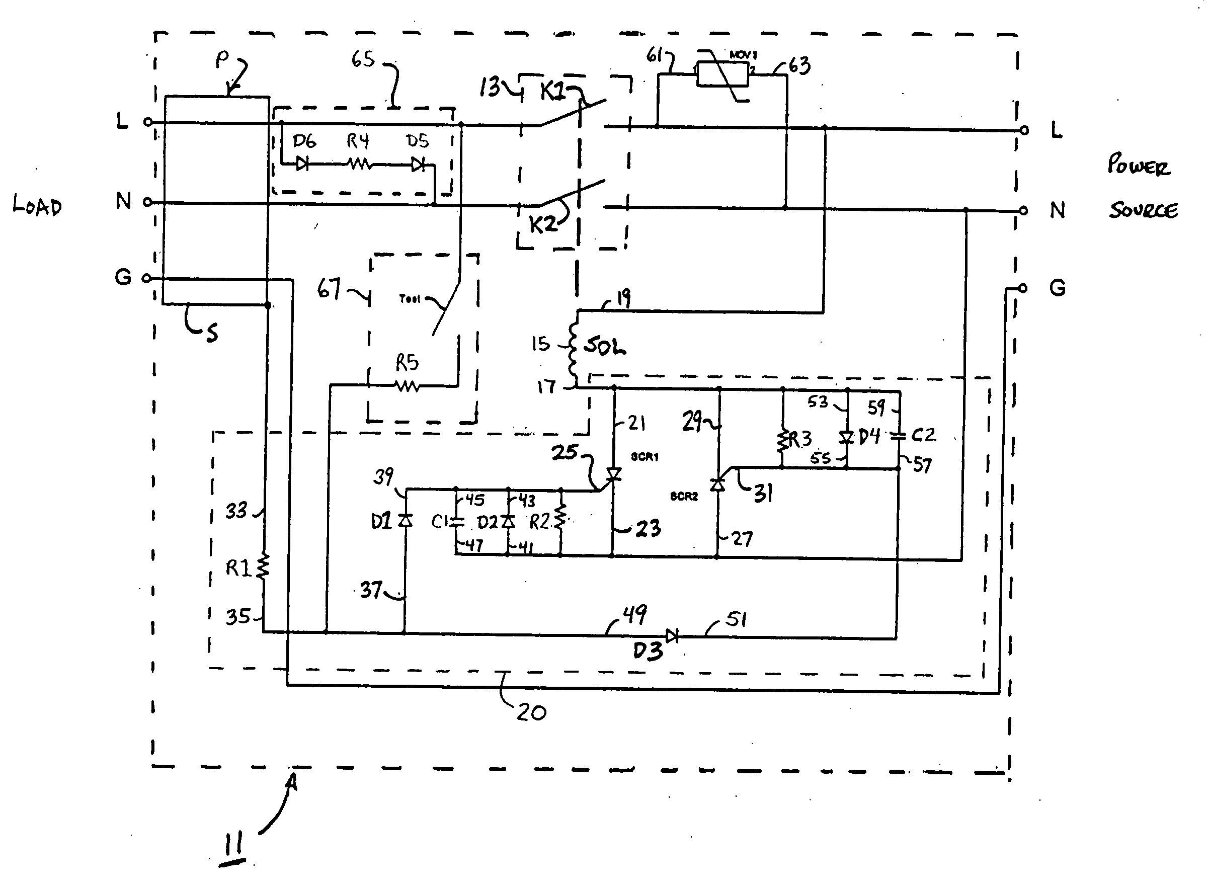
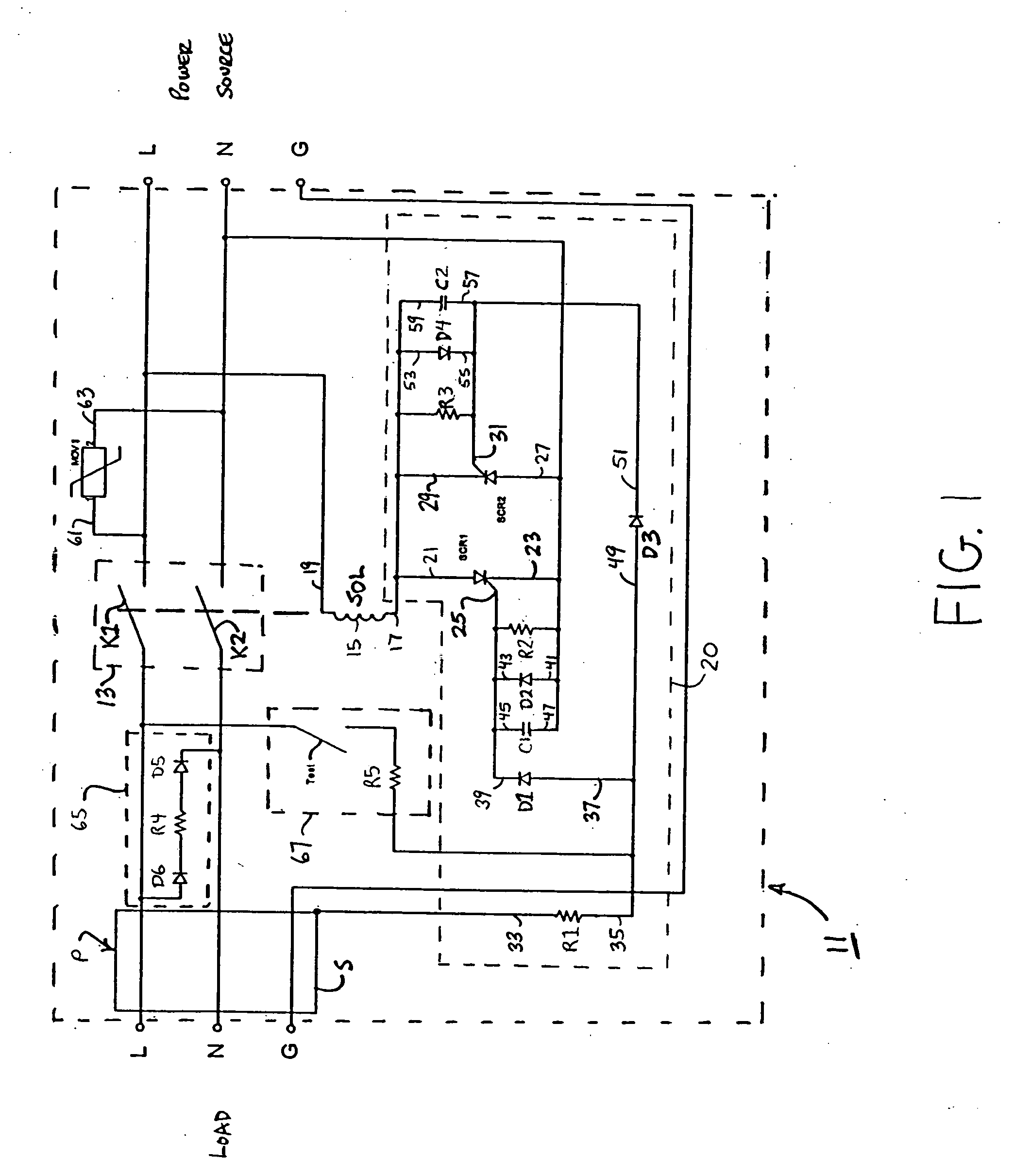
[0025] Referring now to FIG. 1, there is shown a fireguard circuit constructed according to the teachings of the present invention, the fireguard circuit being represented generally by reference numeral 11. Fireguard circuit 11 is designed principally for use as a safety device for a power cable P which connects a power source (i.e., a line) to a load, said power cable P including a power line L, a neutral line N and a ground line G. Each of the power and neutral lines L and N is wrapped with a metal sheath or other similar type of shielded wrapping. The metal sheaths of the power and neutral lines L and N are, in turn, twisted together so as to effectively form a single metal sheath S which surrounds power line L and neutral line N. Ground line G remains electrically isolated from power line L and neutral line N.

[0026] As will be discussed in detail below, fireguard circuit 11 interrupts the flow of current through power line L and neutral line N extending between the power source ...

second embodiment

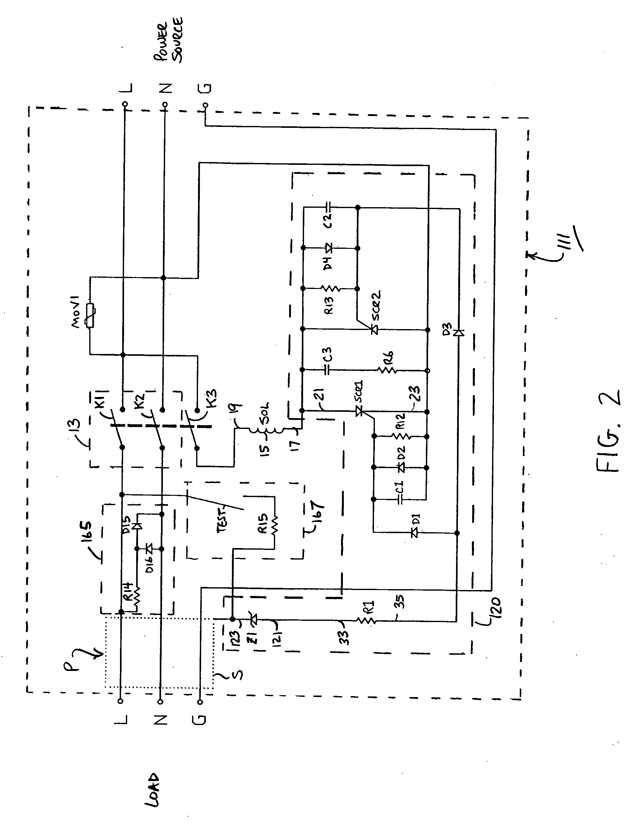
[0056] Specifically, referring now FIG. 2, there is shown a fireguard circuit constructed according to the teachings of the present invention, the fireguard circuit being represented generally by reference numeral 111.

[0057] Fireguard circuit 111 (which may also be referred to herein as safety circuit 111) is identical in all respects with fireguard circuit 11 with four notable distinctions, as will be enumerated below.

[0058] As the first and primary distinction from fireguard circuit 11, fireguard circuit 111 additionally includes a third normally-closed switch K3 (also referred to herein as protection switch K3) which is located in the line which connects second end 19 of winding 15 to the power line L. Solenoid SOL is ganged to third normally-closed switch K3. As a result, solenoid SOL is responsible for selectively controlling the connective position of switches K1, K2 and K3. Specifically, when solenoid SOL is de-energized, switches K1, K2 and K3 remain in their closed positio...

third embodiment

[0062] Referring now FIG. 3, there is shown a fireguard circuit constructed according to the teachings of the present invention, the fireguard circuit being represented generally by reference numeral 211.

[0063] Fireguard circuit 211 is identical in all respects with fireguard circuit 111 with one notable exception: the location of protection switch K3. Specifically, as can be seen in FIG. 3, protection switch K3 is relocated in the line which connects metal sheath S to the input of arc detection subcircuit 120 (i.e., cathode 123 of zener diode Z1). As a result, solenoid SOL connects the output of arc detecetion subcircuit 120 (i.e., anode 21 of first silicon controlled rectifier SCR1) with power line L (as in fireguard circuit 11).


PUM


Abstract

A fireguard circuit for a power cable, which comprises a power line, a neutral line and a metal sheath surrounding the power line and the neutral line, includes a circuit breaker switch located in one of the lines. A solenoid sets the circuit breaker switch in either an open position or a closed position. An arc detection subcircuit connects the metal sheath to the solenoid and causes the solenoid to open the circuit breaker switch upon detecting the presence of an arcing condition between either the power line and the metal sheath or the neutral line and the metal sheath. The power connections for the solenoid and the arc detection subcircuit are derived from the power cable at the power source. In order to prevent the solenoid from overheating and / or burning upon the presence of an arcing condition, a protection switch is ganged to the solenoid and terminates the supply of power to the solenoid when an arcing condition is detected.

Description

CROSS-REFERENCE TO RELATED APPLICATIONS [0001] The present application is a continuation-in-part of U.S. Pat. No. 6,738,241 which issued in the name of Victor V. Aromin on May 18, 2004, U.S. patent application Ser. No. 10 / 783,966 which was filed on Feb. 20, 2004 in the name of Victor V. Aromin, U.S. patent application Ser. No. 10 / 846,358 which was filed on May 13, 2004 in the name of Victor V. Aromin, and U.S. patent application Ser. No. 10 / 886,269 which was filed on Jul. 7, 2004 in the name of Victor V. Aromin, the disclosures of all being incorporated herein by reference.BACKGROUND OF THE INVENTION [0002] The present invention relates generally to electrical safety devices and more particularly to electrical safety devices for a power cable. [0003] Conventional electrical appliances typically receive alternating current (AC) power from a power source, such as an electrical outlet, through a power cable. The power cable enables the electrical appliance, or load, to receive from the...

Claims


Application Information

Patent Timeline
Patent Type & Authority Applications(United States)
IPC IPC(8): H02H9/08H02H3/00H02H1/00H02H7/22
CPCH02H1/0015H02H7/222H02H7/228
Inventor AROMIN, VICTOR V.
Owner TOWER MFG
Why Eureka
Try Eureka