
Component verification method

a verification method and component technology, applied in the field of component verification methods, can solve the problems of missing components, unable to discover operating losses, and extra labor hours for generating component libraries, so as to save loading information labor, easy to read identification information, and fewer labor hours

Inactive Publication Date: 2006-09-21
PANASONIC CORP
View PDF11 Cites 30 Cited by
  • Summary
  • Abstract
  • Description
  • Claims
  • Application Information

AI Technical Summary

Benefits of technology

[0012] With the above construction, the identification information is read from the IC tag attached to the component holder so as to be verified against the prescribed component information. This makes it possible to save the labor of loading information contained in a barcode attached to a supply reel into the memory of a component cassette prior to component verification, as conventionally required, and thus to perform component verification with fewer labor hours. Moreover, since the identification information is read from the IC tag via a wireless communication, it becomes not necessary to move the head or a component cassette, making it possible to reduce operating losses at component mounting time. What is more, since the placement position of the component holder is specified so as to be verified against the prescribed component information, it becomes possible to find a placement error of a component holder if there is any. Here, since the placement position of the component holder is specified based on a state of the signal such as electric waves outputted from the IC tag, there is no need to move the component cassette to specify such placement position, which results in further reduction in operating losses at the time of component mounting.
[0014] Accordingly, when a new component tape is connected, identification information is read from the IC tag of such new component tape and verified against the prescribed component information, making it possible to find and prevent such an error of connecting a wrong component tape.
[0016] With the above construction, the number of components read out in the component number read step is decremented every time a component is taken out from the holder and a warning is issued when the resulting number becomes small. Accordingly, it becomes possible to easily examine the remaining number of components held by the component holder and thus to replace such component holder by a new one before all the components are taken out as well as to reduce operations losses at the time of component mounting.
[0018] With the above construction, since the placement position of the component holder is specified and the identification information of the components held by such component holder is then read from the IC tag so as to generate the component arrangement data. Accordingly, it becomes not necessary to verify by human hands the placement position against the identification information before generating component arrangement data. Instead, component arrangement data is generated quickly and easily simply by placing a component holder in the mounter. Furthermore, in the case where the placement position is specified based on how a signal such as electric waves is outputted from the IC tag, the above construction can further save the labor of moving a component cassette to specify its position.
[0020] With the above construction, since the identification information is read from the IC tag that is attached to the component holder so as to generate the component library, it becomes not necessary to verify the identification information by human hands before generating a component library. As a result, it becomes possible to generate a component library quickly and easily.
[0024] With the above construction, since the IC tag that stores the identification information is attached, it is possible to easily read the identification information from such IC tag via a wireless communication medium. This makes it possible to save the labor of loading information contained in a barcode attached to a reel into the memory of a component cassette prior to component verification, as conventionally required, and thus to perform component verification with fewer labor hours. What is more, since there is no need to move a component cassette to read the identification information, operations losses at the time of component mounting is reduced.

Problems solved by technology

However, there is a problem with the conventional mounter that it is necessary, prior to component verification, to transport barcode information to the memory of each component cassette for each type of tapes to be used.
In general, the number of component tape types to be handled by one mounter is 20 to 50, and sometimes amounts to 100, it is troublesome for workers to transport barcode information to the memory of each component cassette for each of all such types of component tapes.
This requires time for performing a component verification operation and thus causes a problem that operating loss occurs.
Furthermore, it is also a problem that misplacement of components cannot be discovered until a scan operation gets started by the above read unit, i.e., a machine is put into operation.
Moreover, the conventional mounter is required to prepare a component library beforehand, which causes another problem that extra labor hours are required for generating a component library.
Without such information about components to be mounted, a mounter cannot mount such components.

Method used


Image

  • Component verification method
  • Component verification method
  • Component verification method

Examples


first embodiment

[0068] Referring to the drawings, the following describes the mounting system according to the first embodiment of the present invention.

[0069]

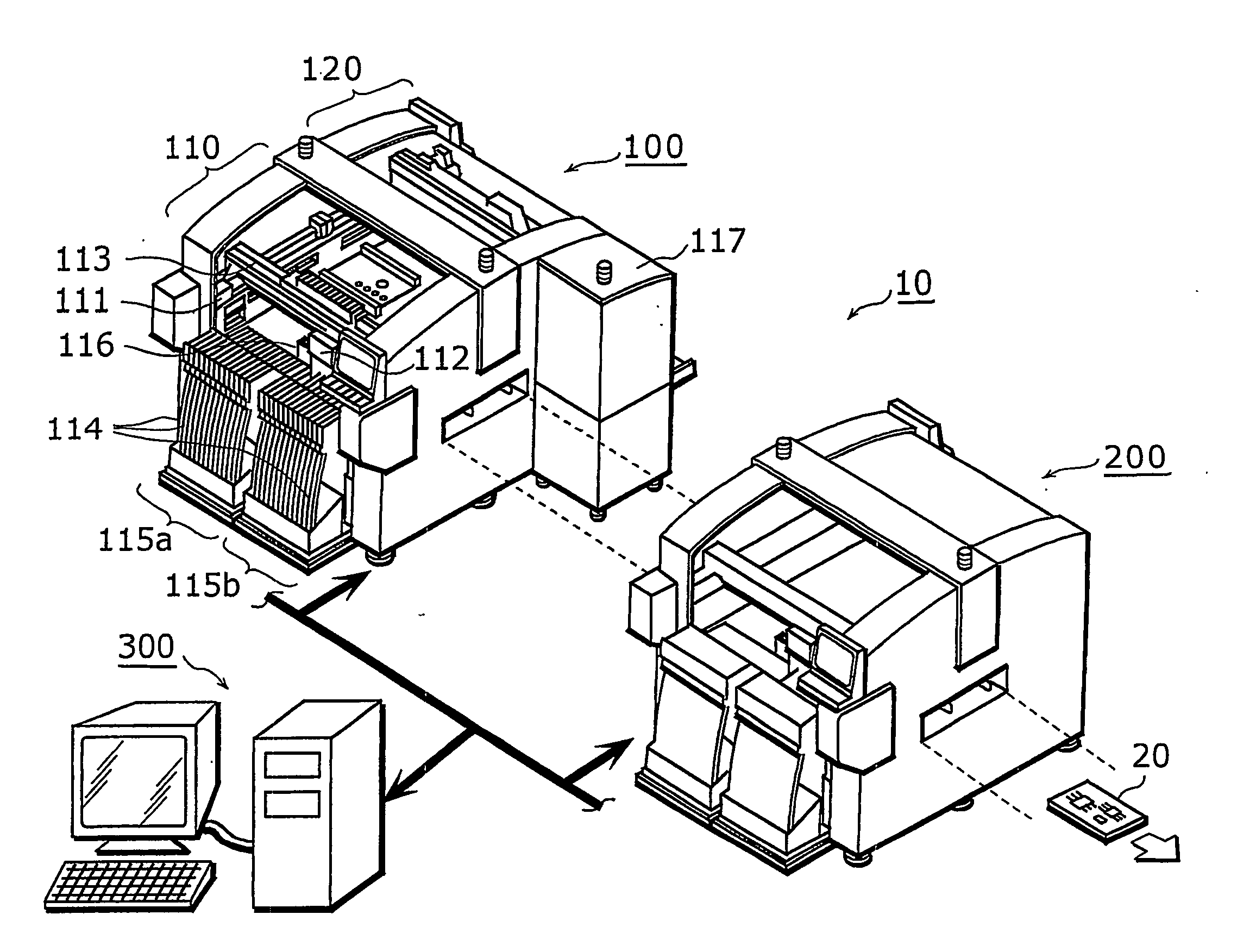
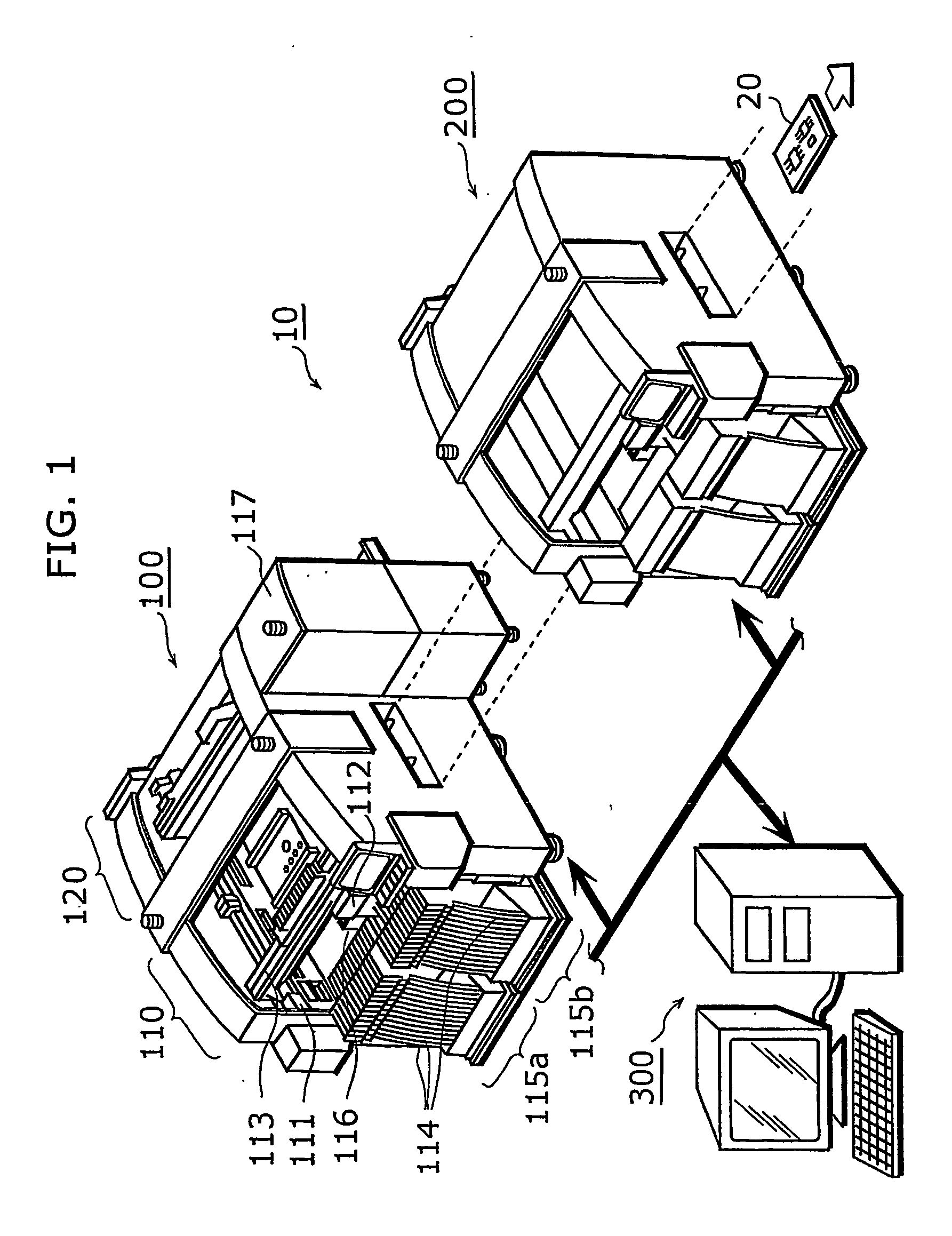
[0070]FIG. 1 shows the entire construction of a mounting system 10 according to the present invention. As shown in the drawing, the mounting system 10 is composed of a plurality (here, two) of mounters 100 and 200, and a component verification apparatus 300. The mounters 100 and 200 form a production line where electronic components are mounted onto a circuit board 20 that is transported downstream. The component verification apparatus 300 optimizes the mounting order of the required electronic components at the start of production, for example, based on information in a variety of databases, and sets and controls the mounters 100 and 200 having provided them with the NC data produced by the optimization.

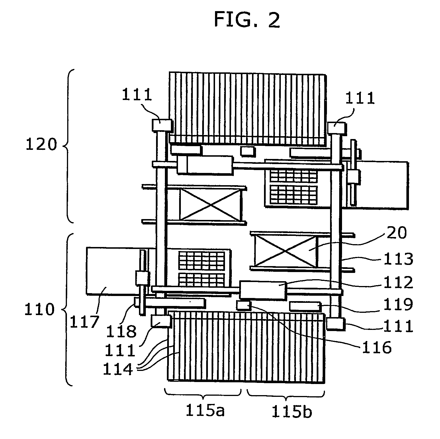
[0071] The mounter 100 is equipped with two stages (a front stage 110 and a rear stage 120) that operate simultaneously and independently ...

second embodiment

[0190] Next, a description is given of a component mounting system according to the second embodiment of the present invention. The configuration of the component mounting system according to the present embodiment is the same as that presented in the first embodiment. However, the component mounting system according to the present embodiment is further capable of performing component arrangement data generation processing and component library generation processing to be described below, prior to component mounting.

[0191]

[0192]FIG. 23 is a flowchart showing component arrangement data generation processing.

[0193] Prior to component mounting, processing as shown in FIG. 23 is performed for generating component arrangement data. The component verification apparatus 300 checks the Z number of each of the components cassettes 114 that have been set, based on information from the respective switches 450 of the component supplying units 115a and 115b shown in FIG. 15 (S1A). Next, the co...

third embodiment

[0206] In the component mounting system 10 according to the first embodiment, the manufacturing information write processing (component management processing) is performed using data that is read from the IC tag attached to a reel, but in the component mounting system according to the third embodiment, manufacturing information write processing is performed using data that is read from the IC tag attached at the front of a component tape.

[0207] The following describes the component mounting system according to the present embodiment with reference to drawings.

[0208]FIG. 26 is a construction diagram showing the construction of the component mounting system according to the present embodiment.

[0209] This component mounting system is comprised of mounters 500 and 600 that mount electronic components 3 onto a printed board 2, as well as a control apparatus 700 that controls these mounters 500 and 600, thereby managing each of the electronic components 3 mounted on the printed board 2...


PUM

PropertyMeasurementUnit
radio frequencyaaaaaaaaaa
widthsaaaaaaaaaa
widthaaaaaaaaaa

Abstract

A component verification method for a mounter (100) that is capable of performing component verification with less labor, is comprised of: a position specification step (S12A) of specifying a placement position in the mounter (100) where a component tape is placed; a read step (S13) of reading component information from an IC tag (426b) that is attached to the component tape or a reel (426); and a verification step (S14) of verifying the component information and the placement position against component arrangement data that indicates components that should be mounted onto the board as well a position where the component tape should be placed.

Description

TECHNICAL FIELD [0001] The present invention relates to a component verification method that is used for mounting electronic components by a mounter, and particularly to a component verification method utilizing integrated circuit (IC) tag. BACKGROUND ART [0002] Mounters that mount electronic components onto boards such as printed board are required to perform verification to see if correct components have been placed on a component cassette before mounting operation. Conventional mounters include one that performs component verification by use of information such as component names and the number of components represented as barcodes (for example, see Japanese Patent publication No.2932670). [0003] A barcode is attached to a reel around which a component tape is wound. Before component verification is carried out, information contained in a barcode is read by a barcode reader to be written into a memory. Note that memory is included in each component cassette to which a reel is loa...

Claims


Application Information

Patent Timeline
Patent Type & Authority Applications(United States)
IPC IPC(8): H05K3/30B23P19/00G06F19/00H05K13/00H05K13/04H05K13/08
CPCH05K13/0452H05K13/08Y10T29/53052Y10T29/4913Y10T29/53174Y10T29/49004Y10T29/49133H05K13/084H05K13/00H05K13/04
Inventor MAENISHI, YASUHIROKONISHI, CHIKASHIYOSHIDA, IKUONISHIDA, HIROYOSHIMATSUMOTO, MASAYAYAMASAKI, AKIHITOYAMAZAKI, TAKUYA
Owner PANASONIC CORP
Learn More