Alignment quality indicator

Inactive Publication Date: 2006-09-21
THE BOEING CO
View PDF12 Cites 4 Cited by
  • Summary
  • Abstract
  • Description
  • Claims
  • Application Information

AI Technical Summary

Benefits of technology

[0009] The present invention provides an alignment tool that may be used during radiographic inspection to achieve proper alignment of a radiation source with the part to be inspected. The present invention further provides an alignment quality indicator that provides accurate feedback to an interpreter of the radiographs thus improving inspection confidence. The present invention provides a

Problems solved by technology

Aircraft nondestructive inspection and evaluation eliminates the need for unnecessary maintenance and aircraft disassembly, which has the potential for creating additional damage and repair problems.
This approach creates problems due to geometric magnification, x-ray or gamma ray source to part distance, and focal spot size.
Currently the laser may not be used for precise alignment of the radio

Method used


Image

  • Alignment quality indicator
  • Alignment quality indicator
  • Alignment quality indicator

Examples


Embodiment Construction

[0024] The following detailed description is of the best currently contemplated modes of carrying out the invention. The description is not to be taken in a limiting sense, but is made merely for the purpose of illustrating the general principles of the invention, since the scope of the invention is best defined by the appended claims.

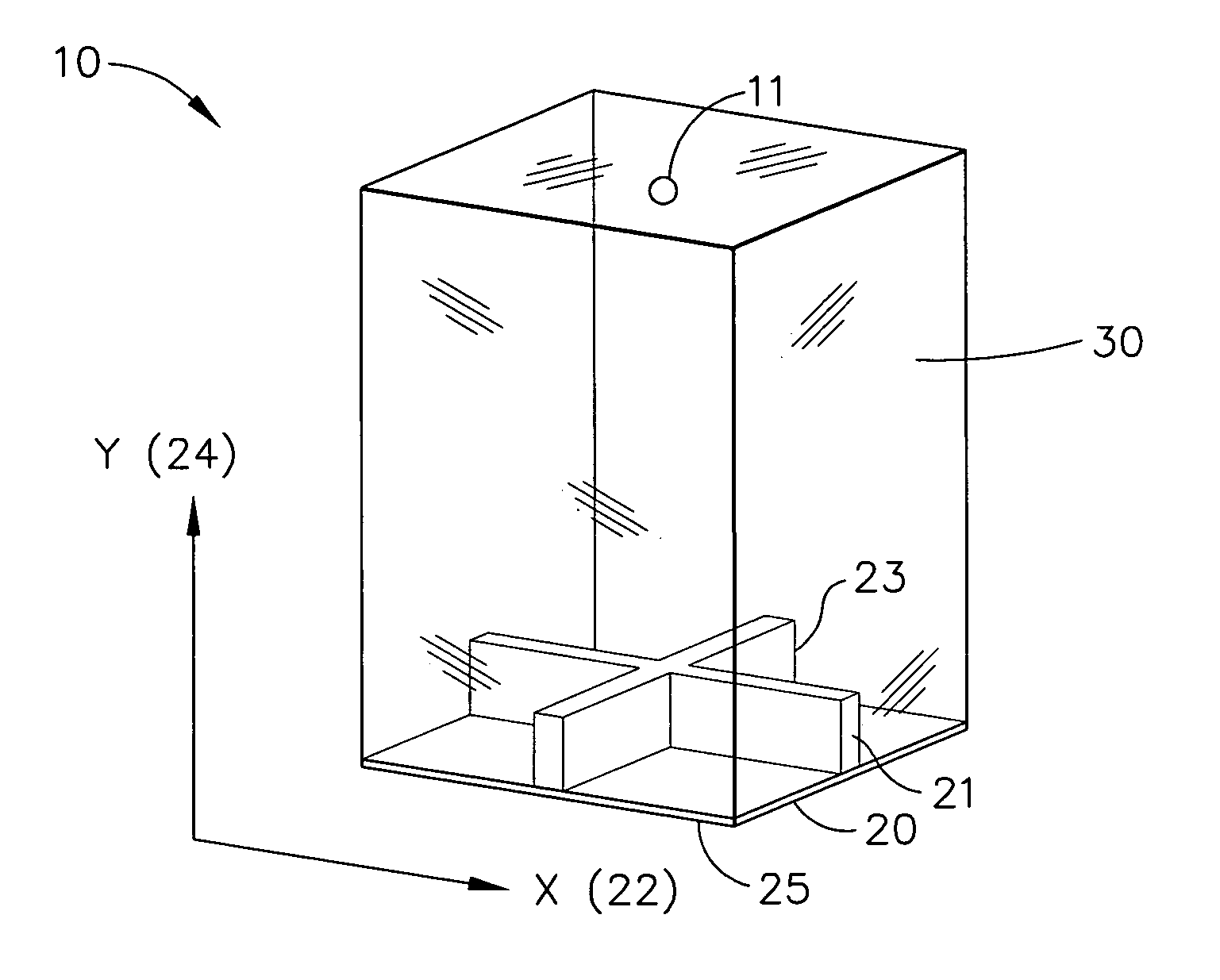
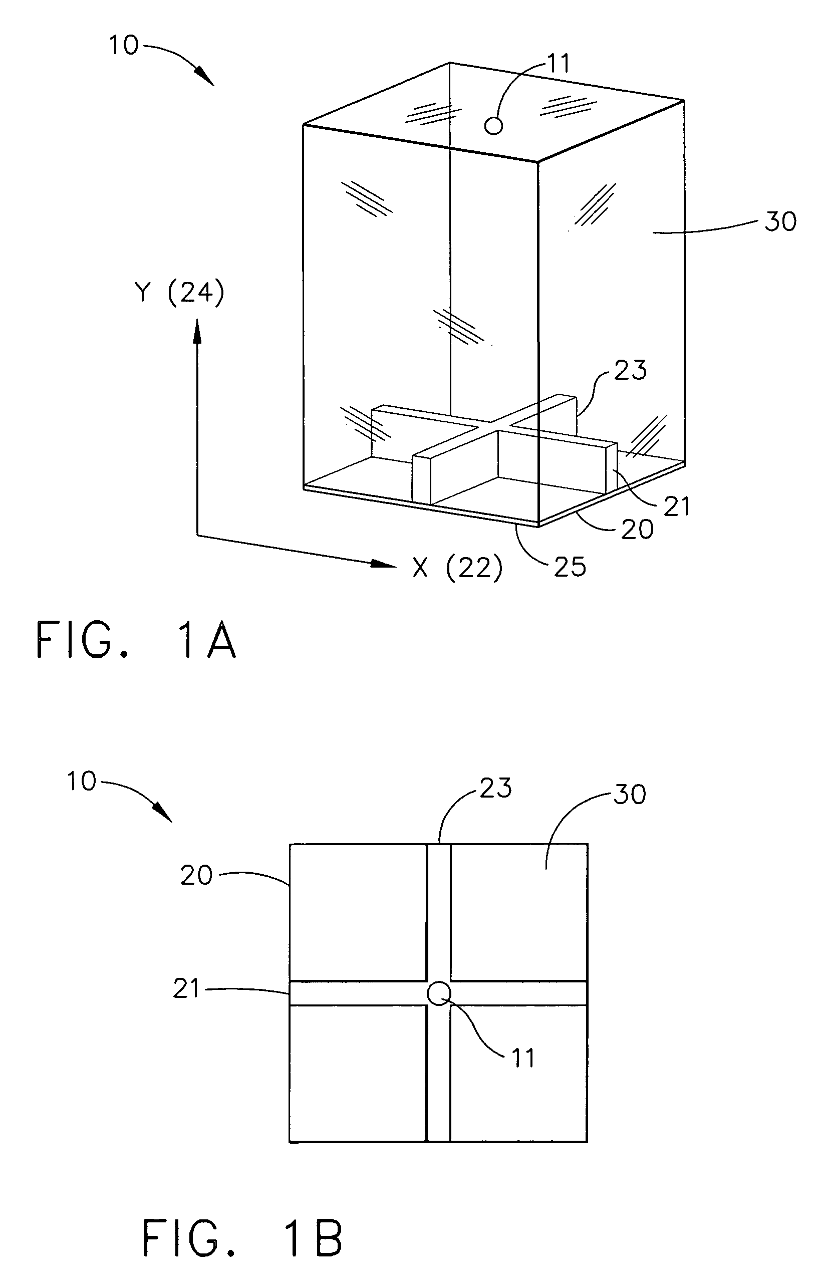
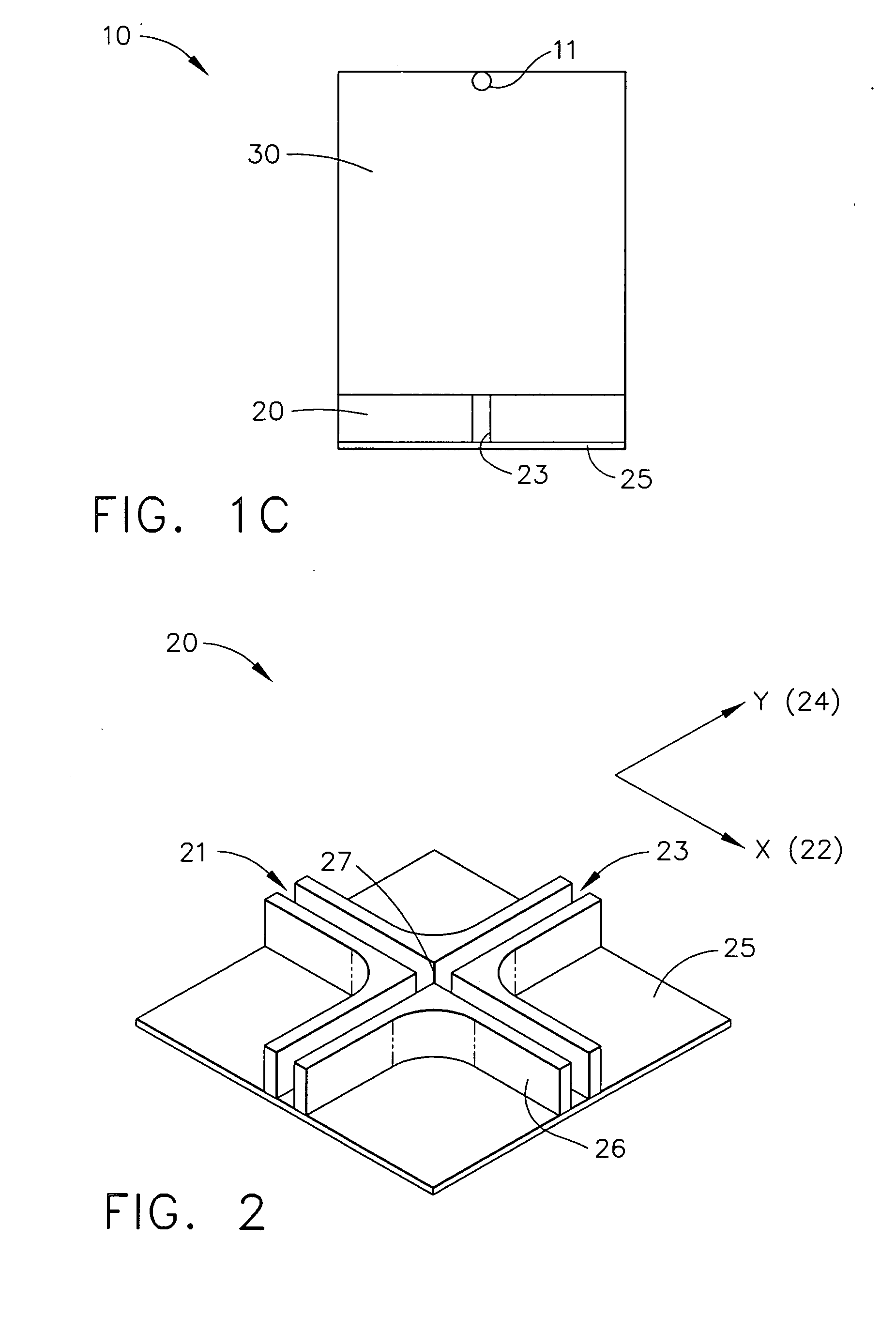
[0025] Broadly, the present invention provides an alignment quality indicator that may be used in conjunction with radiographic inspection techniques. One embodiment of the present invention enables 3-dimensional alignment of a radiation source, such as a x-ray tube or a gamma ray source, with small width defects while eliminating the need to take multiple exposures as typically done in the prior art. Furthermore, one embodiment of the present invention provides alignment quality feedback to the interpreter of the radiographs, such as an inspector or engineer. In one embodiment, the present invention provides an alignment tool that may be visible in a...


PUM


Abstract

An alignment tool includes a base, a column, and a ball. The base is manufactured from a material with a high material density and includes a crosshair. The column is machined out of an optical transparent material and is attached to the base. The ball is positioned within the column at the end opposite to the base and above the center of the crosshair. The alignment tool may not only be used to properly align a radiation source with an area of interest of a part to be inspected but also as an alignment quality indicator providing information of proper alignment to an interpreter of the radiograph taken. Therefore, the need to take multiple exposures can be eliminated. The alignment quality indicator is suitable for, but not limited to, applications in the aerospace industry, such as nondestructive testing and evaluation of airframes during aircraft manufacturing, maintenance, and repair.

Description

BACKGROUND OF THE INVENTION [0001] The present invention generally relates to radiographic inspection techniques and, more particularly, to an alignment tool and to a radiographic inspection process. [0002] Radiographic inspection techniques have been used for over half a century for nondestructive testing of weld, castings, and forgings in a variety of industries. Radiographic inspection techniques are currently used, for example, for the evaluation of aging and contemporary aircraft, as well as during aircraft manufacturing, maintenance, and repair. Radiographic inspection may be employed beneficially to detect hidden defects, such as cracks, gaps, and corrosion, to assess internal damage, and to detect foreign objects, for example, in airframe structures. Aircraft nondestructive inspection and evaluation eliminates the need for unnecessary maintenance and aircraft disassembly, which has the potential for creating additional damage and repair problems. High-energy radiation can be...

Claims


Application Information

Patent Timeline
IPC IPC(8): G01C15/00
CPCG01N23/18G01N23/083
Inventor VACCARO, CHRISTOPHER M.
Owner THE BOEING CO
Why Eureka
Try Eureka