Multi-air conditioner peak power control system and control method thereof

a multi-air conditioner and control system technology, applied in the integration of power network operation systems, instruments, heat measurement, etc., can solve the problems of inability to quickly perform peak power control of multi-air conditioner systems in response to the varied total reference power consumption, and inability to quickly perform peak power control of multi-air conditioner systems

Inactive Publication Date: 2006-09-21
LG ELECTRONICS INC
View PDF16 Cites 18 Cited by
  • Summary
  • Abstract
  • Description
  • Claims
  • Application Information

AI Technical Summary

Benefits of technology

[0020] In a feature of the present invention, peak power control of a multi-air conditioner system is performed in connection with total reference power consumption in a building, so that the peak power control is rapidly performed even in the case of a variation in the total reference power consumption, thereby preventing the interruption of power supply to the entire building in the case that power consumption exceeds the total reference power consumption.

Problems solved by technology

However, the conventional multi-air conditioner central control system having the configuration and operational behavior described above can only perform the peak power control of the outdoor units 2 and indoor units 3 connected via the network.
Consequently, the central control system cannot perform the peak power control of the multi-air conditioner system relatively to the entire building.
However, in the conventional central control system, peak power control of the multi-air conditioner system cannot be rapidly performed in response to the varied total reference power consumption.
Because of this, if the total power consumption in the entire building exceeds the total reference power consumption, operations of electric devices equipped in the building may be forcibly interrupted.

Method used


Image

  • Multi-air conditioner peak power control system and control method thereof
  • Multi-air conditioner peak power control system and control method thereof
  • Multi-air conditioner peak power control system and control method thereof

Examples


Embodiment Construction

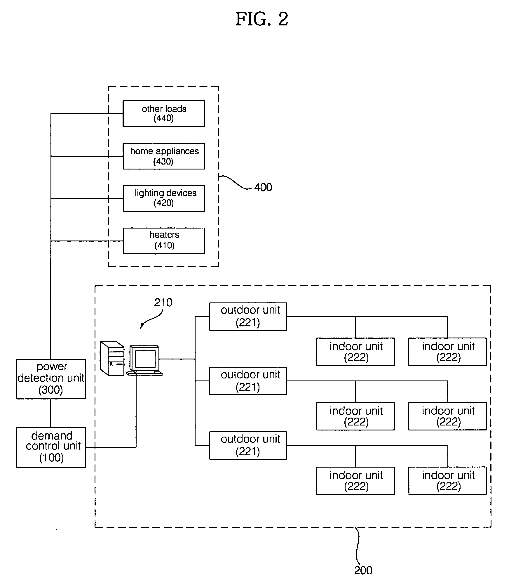
[0028]FIG. 2 is a block diagram showing the overall configuration of a multi-air conditioner peak power control system according to the present invention.

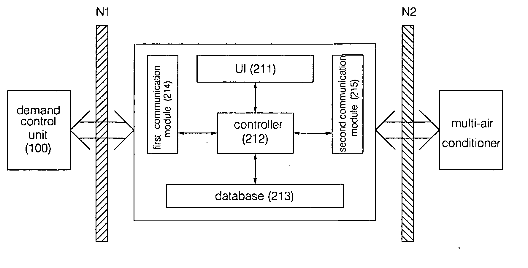
[0029] The multi-air conditioner peak power control system according to the present invention comprises a multi-air conditioner system 200 including a plurality of outdoor units 221 and a plurality of indoor units 222, other electric devices 400 installed in a building where the multi-air conditioner system 200 is constructed and including a plurality of electric appliances, a power detection unit 300 for detecting total power consumption in the building, and a demand control unit 100 for controlling the total power consumption in the building.

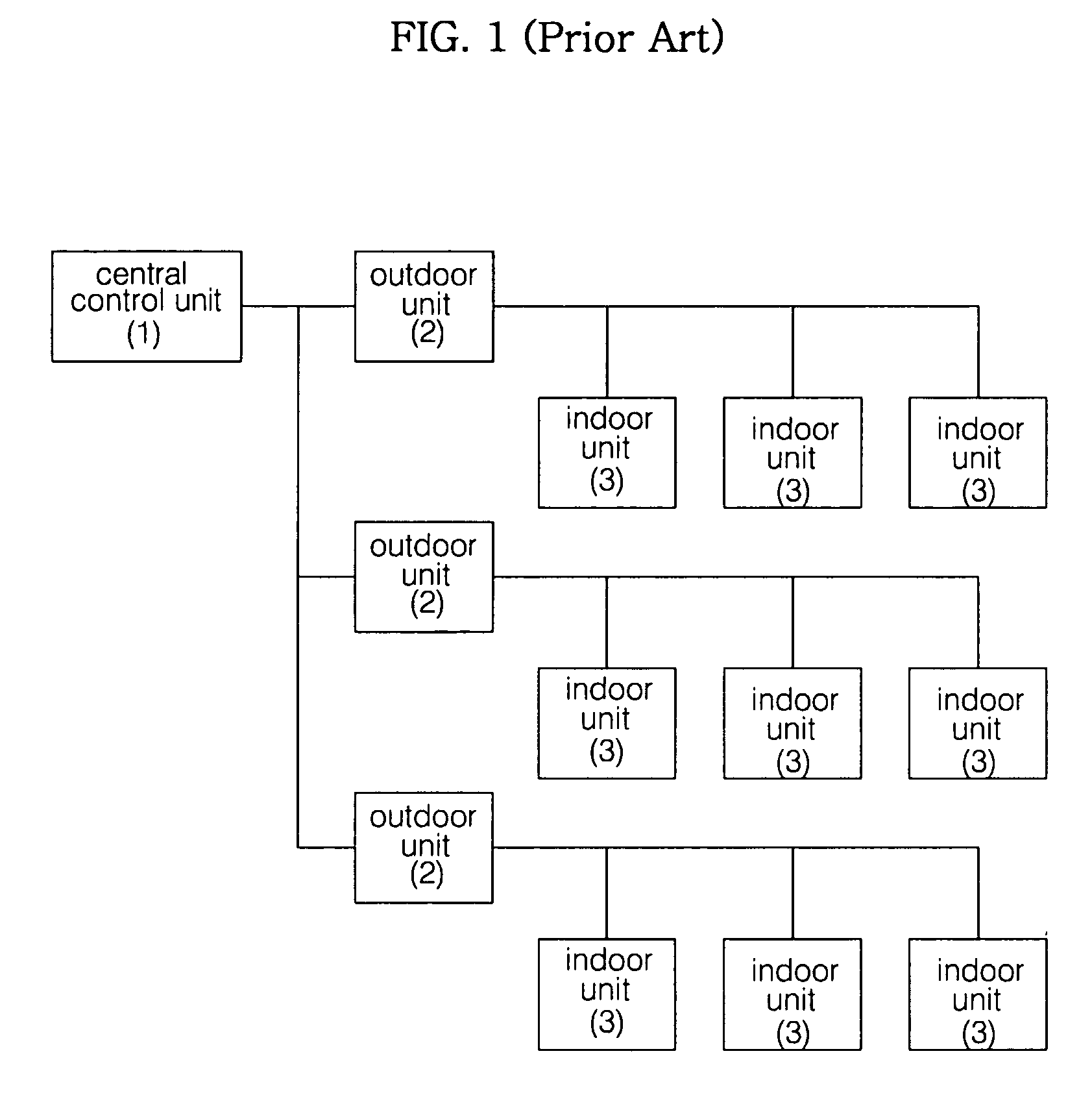
[0030] The multi-air conditioner system 200 comprises a plurality of multi-air conditioners (221 and 222), each of which includes a certain one of the outdoor units 221 and two or more ones of the indoor units 222 connected to the certain outdoor unit 221. The multi-air conditioner system 2...


PUM


Abstract

Disclosed herein are a multi-air conditioner peak power control system and a control method thereof. The peak power control system comprises a central control unit for controlling a multi-air conditioner system including a plurality of multi-air conditioners each having an outdoor unit and a plurality of indoor units in an integrated manner, and operating the multi-air conditioner system at a reference operation rate, and a demand control unit for sending/receiving data to/from the central control unit to control power consumption of the multi-air conditioner system such that the power consumption is less than total reference power consumption allocated to a building. The control method of the peak power control system adjusts the total power consumption in the building such that the total power consumption does not exceed the total reference power consumption in a more efficient and convenient way, thereby reducing excessive cost burden due to power over-consumption and significantly enhancing user convenience.

Description

BACKGROUND OF THE INVENTION [0001] 1. Field of the Invention [0002] The present invention relates to a multi-air conditioner peak power control system and a control method thereof wherein a central control unit of a multi-air conditioner system and a demand control unit for monitoring total power consumption in a building in which the multi-air conditioner system is installed are adapted to cooperate with each other to adjust reference power consumption for peak power control of the multi-air conditioner system so that electric power supplied to the building is effectively utilized. [0003] 2. Description of the Related Art [0004] Recently, air conditioners have entered into widespread use. According to such a trend, a multi-type air conditioner has been developed and made commercially available which includes two or more indoor units installed in individual rooms of a home or individual offices of a building, and an outdoor unit connected in common with the indoor units. A plurality...

Claims


Application Information

Patent Timeline
Patent Type & Authority Applications(United States)
IPC IPC(8): H04M11/00
CPCF24F11/0086F24F2011/0067H02J3/14H02J2003/143Y02B70/3225Y02B70/3266Y02B70/3275Y04S20/222Y04S20/242Y04S20/244Y04S20/224F24F2011/0047F24F11/30F24F2140/60F24F11/54H02J2310/14Y02B70/30H02J2310/60F24F11/47F24F11/46H02J3/144
Inventor JUNG, JAE SIKYOUN, SANG CHULJEON, DUCK GU
Owner LG ELECTRONICS INC
Why Eureka
Try Eureka