
Method of controlling vehicle driving system

a technology of driving system and vehicle, which is applied in the direction of machine/engine, rider propulsion, engine starter, etc., to achieve the effect of reducing the upper limit rotational speed, reducing the noise level of the revolving engine, and reducing the quantity of accelerator pedals

Inactive Publication Date: 2006-09-21
MIYAO TAKAYUKI
View PDF11 Cites 19 Cited by
  • Summary
  • Abstract
  • Description
  • Claims
  • Application Information

AI Technical Summary

Benefits of technology

[0021] Thus, it is the object of the present invention to provide a method of controlling a vehicle driving system that can set the conditions under which the rotational motion of the flywheel is reaccelerated by means of the engine in a flywheel energy accumulation / driving system not comprising a differential gear (see FIG. 1) and also in a differential gear type flywheel energy accumulation / driving system. (Arrangement of the Method of Controlling a Vehicle Driving System)
[0038] With this arrangement for a method of controlling a vehicle driving system according to the invention, the flywheel is driven intermittently for the range of Acco≦Acc<1.0 on the basis of the lower limit rotational speed Nfc of the flywheel obtained by adding a predetermined value dNe to the value of Nei so that it is possible to drive the flywheel to rotate without stalling it. Additionally, since the lower limit rotational speed Nfco is held to a constant level that is determined to at Acco in the range of Acco≦Acc<1.0 also for the range of 0≦Acc<Acco, the fuel efficiency is prevented from falling.
[0040] With this arrangement, when the engine is restarted to supply rotational energy to the flywheel, while operating on the fuel economizing characteristic curve, the engine drives the flywheel in such a way it reduces the upper limit rotational speed Nfm of the flywheel according to the decrease of the pedaled quantity Acc of the accelerator pedal. Therefore, as the pedaled quantity of the accelerator pedal is decreased, the largest rotational speed of the engine is reduced to by turn reduce the purring noise level of the revolving engine so that the driver can perceive that the engine is operating normally and smoothly without having any strange feeling.
[0041] Preferably, in a method of controlling a vehicle driving system according to the present invention, the Acco is equal to the low level pedaled quantity of the accelerator pedal corresponding to the point on the fuel economizing characteristic curve (Fec) where a rapid fall of the curve starts. With this arrangement, it is possible to reliably prevent a fall of fuel efficiency within the range of 0≦Acc<Acco.
[0042] Preferably, in a method of controlling a vehicle driving system according to the present invention, the value of dNe is equal to about 100 rpm. With this arrangement, it is possible to reliably prevent the flywheel from stalling when the flywheel is reaccelerated.

Problems solved by technology

However, no formula that corresponds to the above described formula (b) and provides the base for controlling the differential gear type flywheel energy accumulation / driving system has been developed so far.

Method used


Image

  • Method of controlling vehicle driving system
  • Method of controlling vehicle driving system
  • Method of controlling vehicle driving system

Examples


Embodiment Construction

[0052] Now, a method of controlling a vehicle driving system according to the present invention will be described in greater detail by referring to accompanying drawings that illustrate preferred embodiments of the invention. However, it may be clear that the present invention is by no means limited to the embodiments that will be described hereinafter.

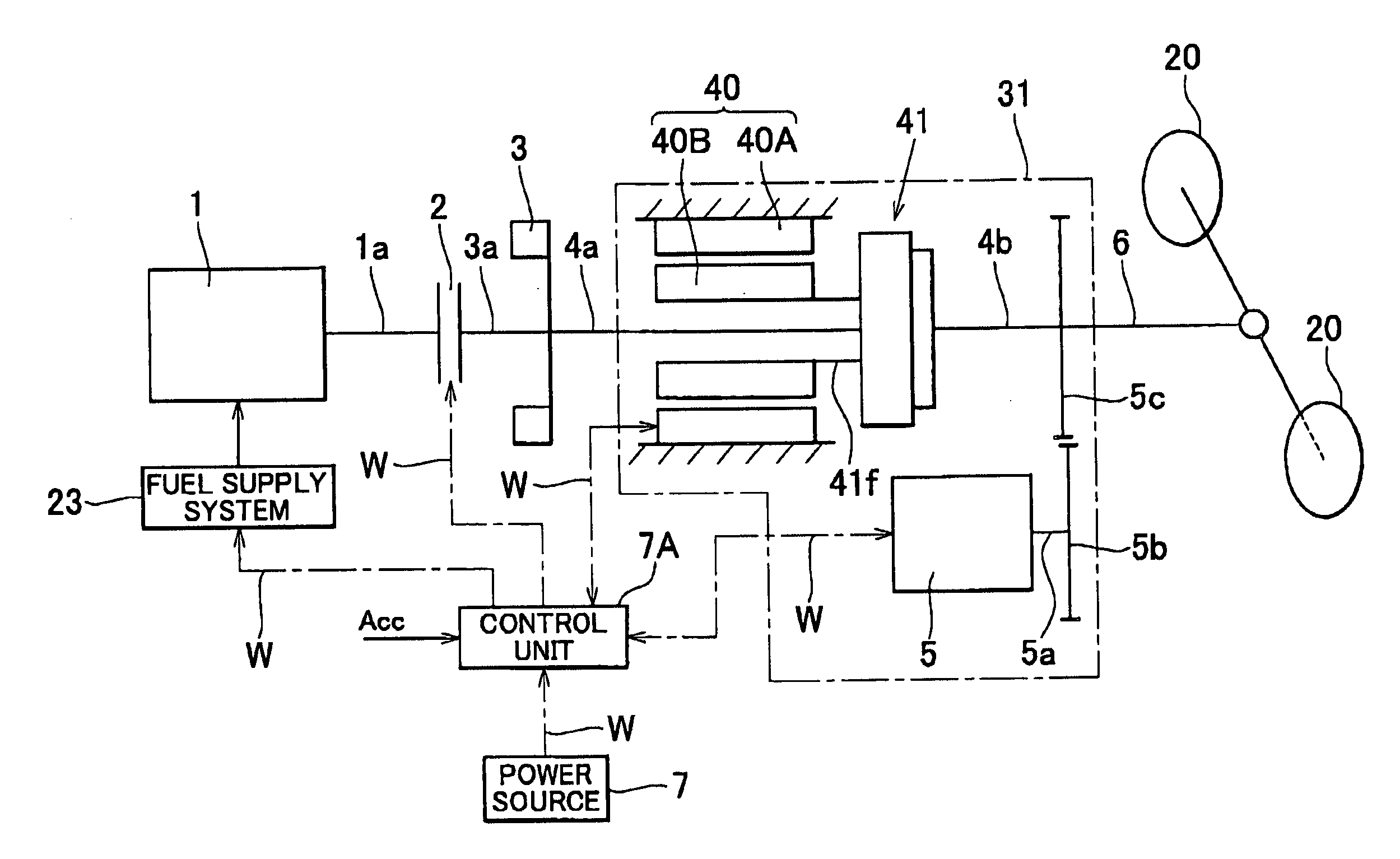
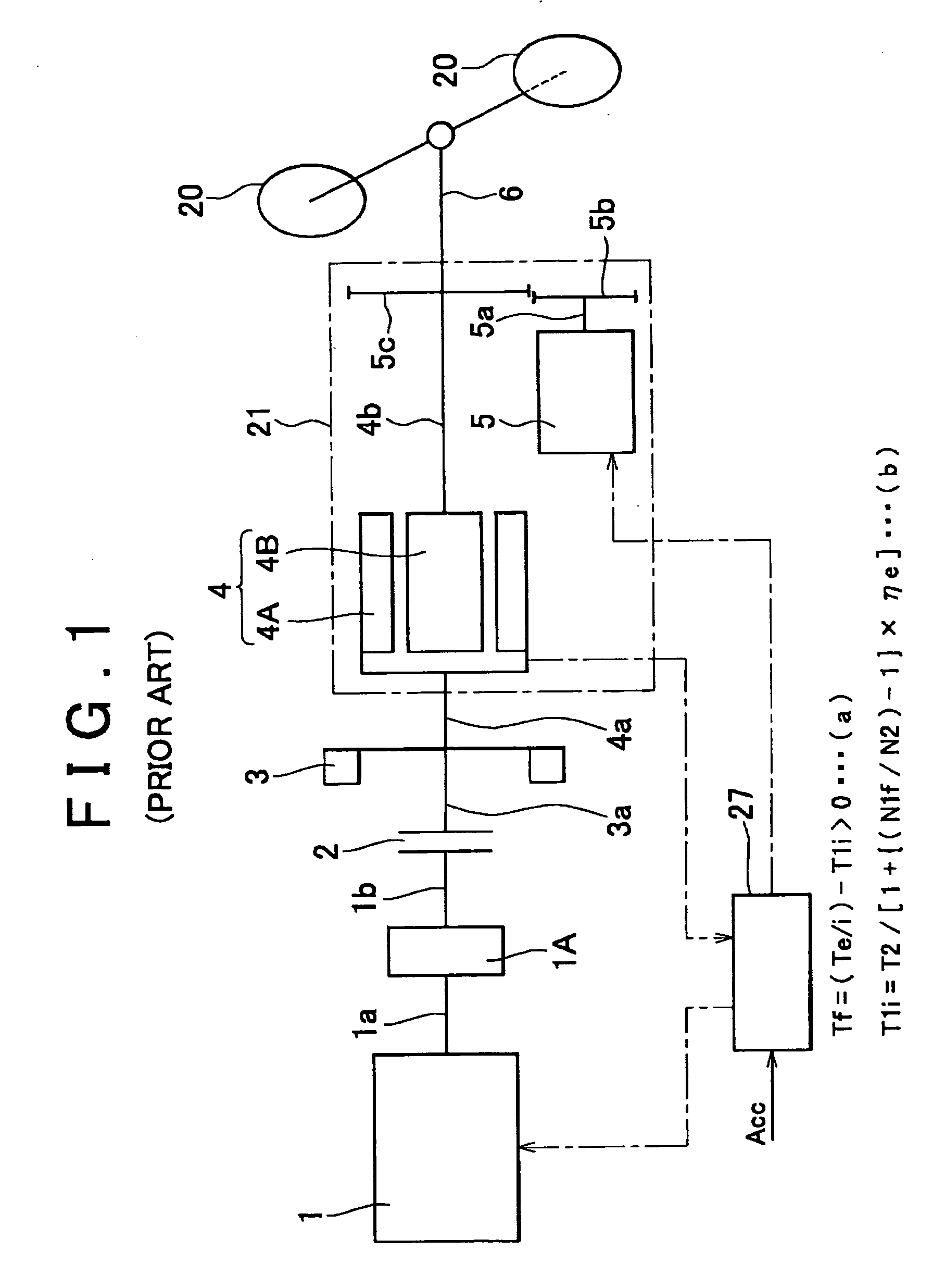
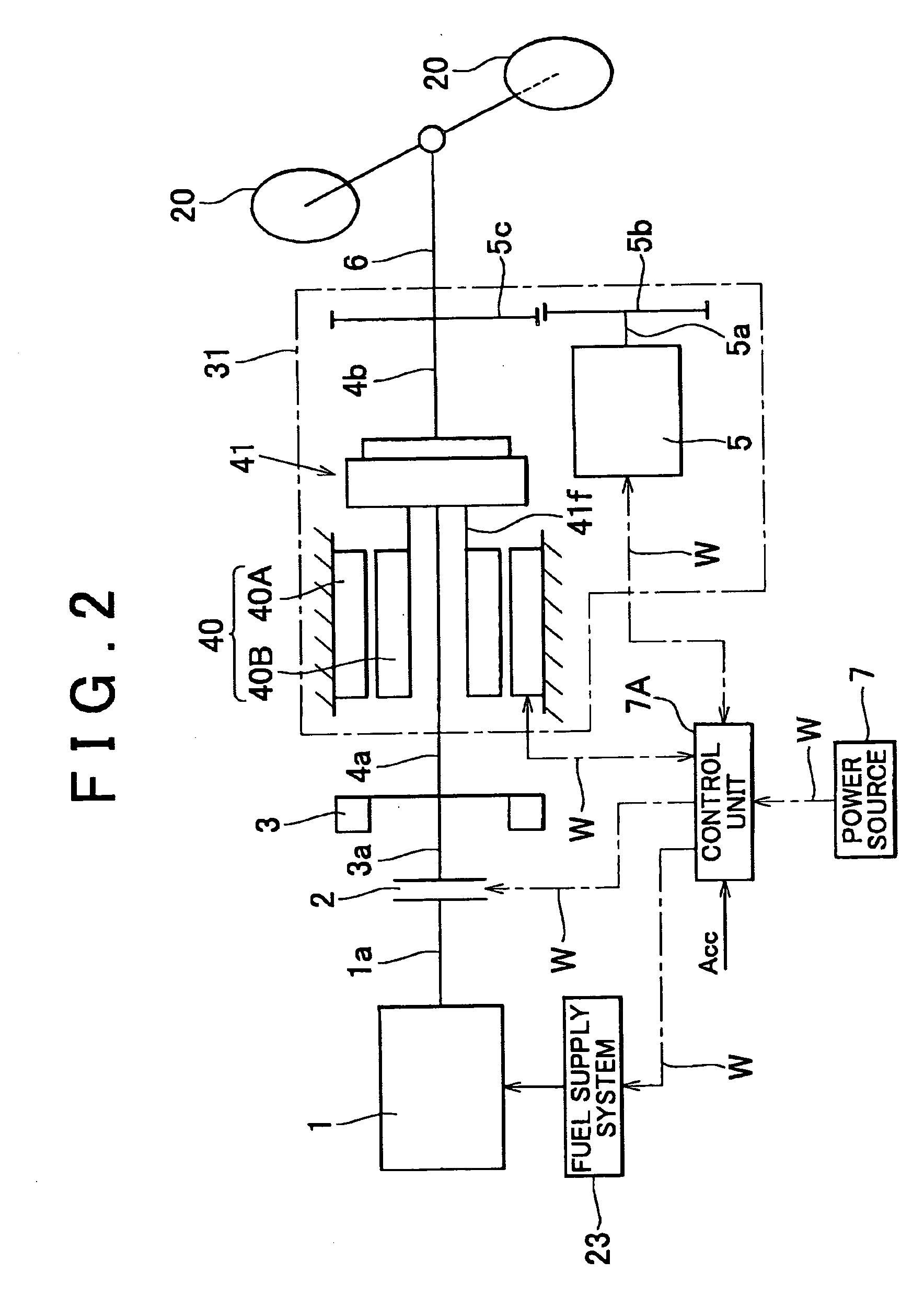
[0053] Firstly, before describing the method, a vehicle driving system that can be used with a control method according to the present invention will be described. FIG. 2 schematically illustrates a flywheel energy accumulation / driving system as an example of such a vehicle driving system. While the control method according to the invention is applicable to the part of the mechanical system of a flywheel energy accumulation / driving system that does not use a differential gear as illustrated in FIG. 1, the control method of the present invention is applied to a flywheel energy accumulation / driving system that uses a differential gear ...


PUM


Abstract

With a method of controlling a vehicle driving system comprising a flywheel for accumulating the output of engine as energy, a motor generator to be driven by the engine to generate electricity and an output shaft interlocked with the drive wheels of a vehicle, provided that (A) the lower limit rotational speed of the flywheel at the time of restarting the engine to supply rotational energy to the flywheel while decelerating the flywheel by not operating the engine is Nfc, (B) the largest power of the engine operating on the fuel economizing characteristic curve is Pem, (C) the pedaled quantity of the accelerator pedal is Acc and (D) the pedaled quantity of the accelerator pedal for the largest power output of the engine is Acc=1.0, (E) when 0≦Acc≦1.0, ① the power level of Acc×Pem=Pei is determined, ② the rotational speed Nei of the engine is determined for power level Pei on the fuel economizing characteristic curve and ③ the value obtained by adding a predetermined value dNe to the value of Nei is defined as the lower limit rotational speed Nfc.

Description

BACKGROUND OF THE INVENTION [0001] 1. Field of the Invention [0002] This invention relates to a method of controlling a vehicle driving system adapted to accumulate power output intermittently from a thermal engine in a flywheel as rotational energy and only a necessary part of the accumulated energy is taken out to the output shaft of a power dividing type power transmission unit. Thermal engines to which the present invention is applicable include internal-combustion engines and external-combustion engines. Generally, power dividing type power transmission unit comprises a power dividing mechanism, which may be a type using a motor generator where both an inner rotor and an outer rotor rotate or a type where an ordinary motor generator is connected to the reactionary shaft of a differential gear. [0003] 2. Description of the Related Art [0004] Known methods of controlling a vehicle driving system of the type under consideration include a control method of accumulating energy in a ...

Claims


Application Information

Patent Timeline
Patent Type & Authority Applications(United States)
IPC IPC(8): B60K6/00B60K6/30B60L50/10B60K6/445B60K6/48
CPCB60K6/30Y02T10/70B60W10/06B60W10/08B60W20/00F02N5/04F02N11/04Y02T10/6221Y02T10/6286Y10S903/96B60L11/14B60L11/16B60L15/20B60L2240/421B60L2240/423B60L2240/441B60L2240/443B60L2240/507B60L2260/22B60L2260/26Y10T477/60Y02T10/7077Y02T10/7027Y02T10/7033Y02T10/7275Y02T10/642B60K6/48Y02T10/72B60L50/16B60L50/30Y02T10/62Y02T10/64Y02T10/7072B60K2006/268B60W20/11
Inventor MIYAO, TAKAYUKI
Owner MIYAO TAKAYUKI
Features
  • Generate Ideas
  • Intellectual Property
  • Life Sciences
  • Materials
  • Tech Scout
  • Unparalleled Data Quality
  • Higher Quality Content
  • 60% Fewer Hallucinations
Learn More