Solid-state image device, driving method thereof, and camera

Inactive Publication Date: 2006-09-21
PANASONIC CORP
View PDF0 Cites 22 Cited by
  • Summary
  • Abstract
  • Description
  • Claims
  • Application Information

AI Technical Summary

Benefits of technology

[0021] In this way, it is possible to realize a method of driving a solid-state imaging device which is capable of suppressing the occurrence of horizontal shading accompanying a reduction in consumption electricity without increasing the signal reading-out time. In addition, it is possible to realize a method of driving a solid-state imaging device which is capable of preventing a problem of a decrease in the dynamic ranges.
[0022] With the present invention, it is possible to control the variation of the power supply voltage accompanying a current variation in the horizontal signal reading-out period during which the pixel signals held in the charge hol

Problems solved by technology

However, the above-mentioned solid-state imaging device, disclosed in the Japanese Laid-open Patent Application No. 9-247537, which changes a current at the transition boundary between a vertical signal reading-out period and a horizontal signal reading-out period has a problem described below.
The variatio

Method used


Image

  • Solid-state image device, driving method thereof, and camera
  • Solid-state image device, driving method thereof, and camera
  • Solid-state image device, driving method thereof, and camera

Examples


first embodiment

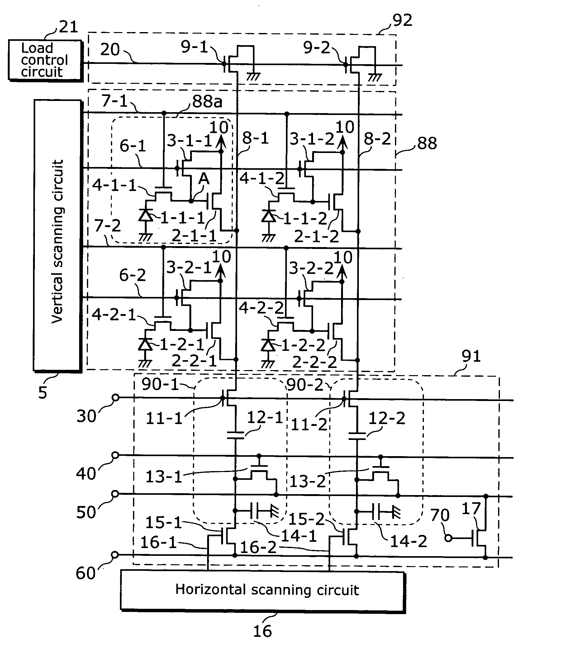
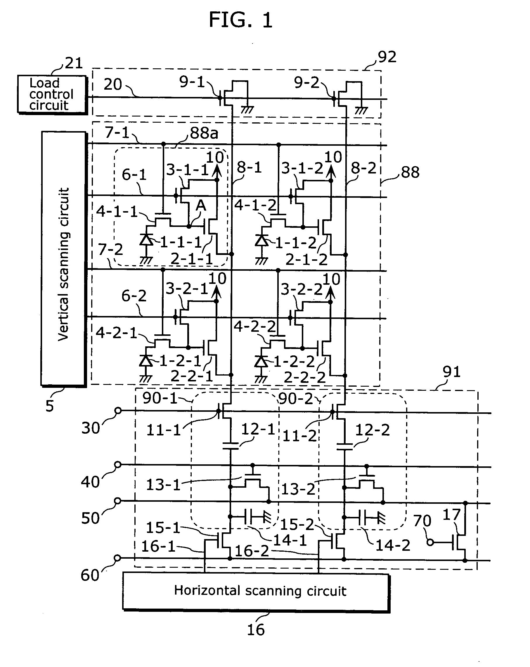
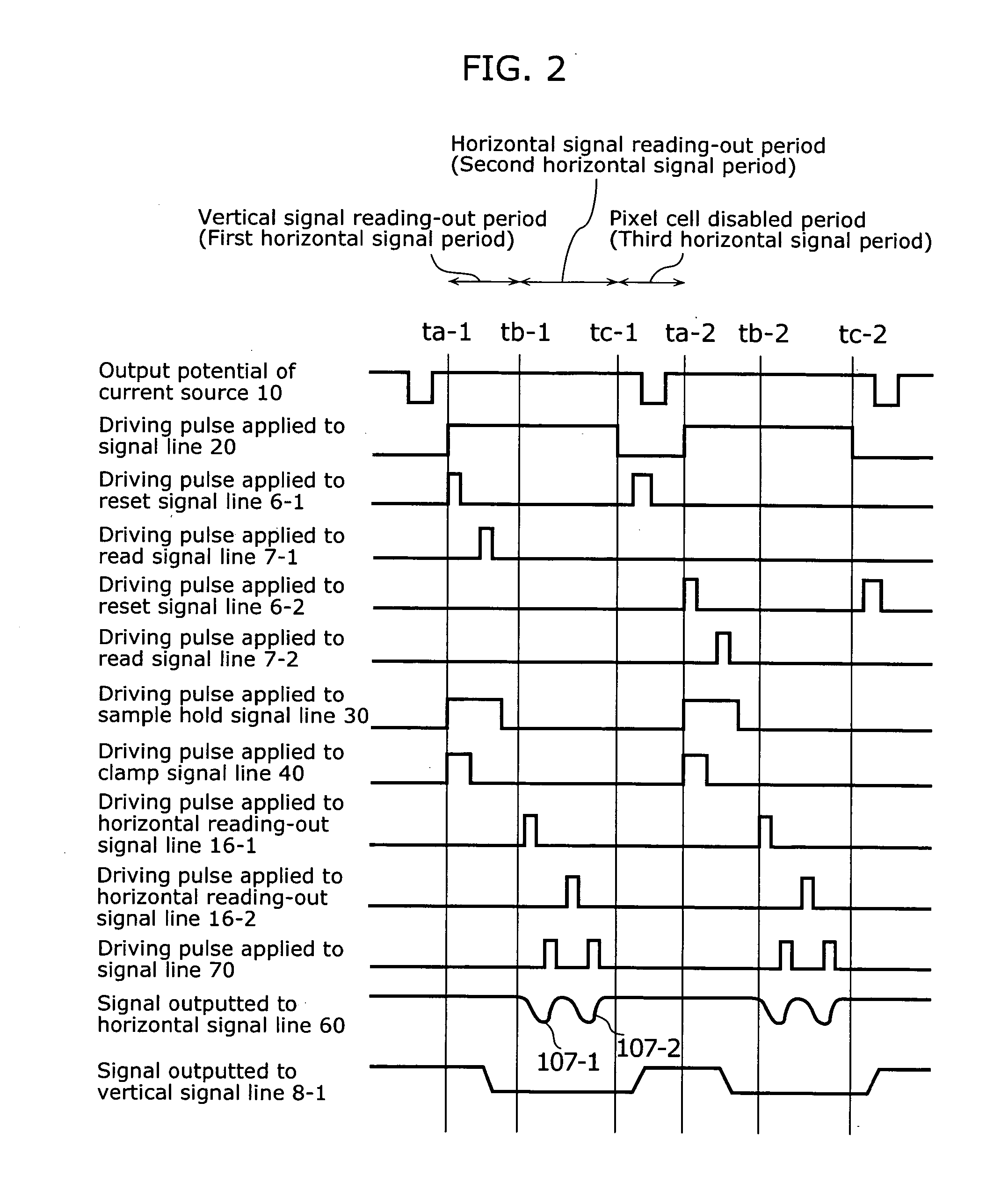
[0032] This embodiment relates to a solid-state imaging device which controls power supply variation, accompanying a reduction in consumption electricity, in a horizontal signal reading-out period by performing control of a current flowing in the amplifying transistors of pixel cells, not immediately before the starting time of the horizontal signal reading-out period but after the ending time of the horizontal reading-out period. In particular, it relates to a solid-state imaging device which allows only particular pixel cells to selectively output pixel signals by performing a periodic transition of HIGH potential and LOW potential in the power supply voltage instead of keeping the power supply voltage supplied to the respective pixel cells constant. Performing control of a current of the amplifying transistors between the ending time of the horizontal signal reading-out period and the time of resetting the selection of pixel cells makes it possible to control variation of the pow...

second embodiment

[0067]FIG. 4 is a diagram showing the structure of a camera in a second embodiment of the present invention.

[0068] This camera 80 is made up of a solid-state imaging device 82 shown in the first embodiment, a DSP (Digital Signal Processor) 81 which applies various kinds of driving pulses to the solid-state imaging device 82 and a power supply output circuit 87 which is placed between the solid-state imaging device 82 and the DSP 81 and supplies the power supply 10 to the pixel cells 88a.

[0069] The power supply output circuit 87 is made up of resistor 85 and 86 which generate LOW potential of the power supply pulse, a power supply 83 which generates HIGH potential of the power supply pulse, and a switch 84 which switches the potential of the power supply pulse between HIGH and LOW.

[0070] In the camera 80 of this embodiment, various kinds of driving pulses are applied from the DSP 81 to the solid-state imaging device 82, and the solid-state imaging device 82 operates according to t...


PUM


Abstract

An object of the present invention is to provide a solid-state imaging device which is capable of suppressing horizontal shading in which light and shade is generated on a display screen in a left to right direction, without increasing the signal reading-out time, and the driving method of the device. It includes pixel cells, vertical signal lines, load transistors, sampling capacitors, a horizontal signal, and a load control circuit. The load control circuit controls the load transistors functioning as loads to become disabled between the ending time of the horizontal signal reading-out period in which pixel signals are read out from the sampling capacitors to a horizontal signal line and the starting time of the vertical signal reading-out period in which pixel signals are read out from the pixel cells to vertical signal lines.

Description

BACKGROUND OF THE INVENTION [0001] (1) Field of the Invention [0002] The present invention relates to a MOS solid-state imaging device and a driving method thereof, and in particular to a technique for suppressing image deterioration accompanying a current variation in the solid-state imaging device. [0003] (2) Description of the Related Art [0004] With regard to a MOS solid-state imaging device, there is a demand for reducing electricity consumption. As a solid-state imaging device which satisfies a demand like this, a technique of controlling a current flowing in the amplifying transistors placed in pixel cells has been disclosed in the Japanese Laid-open Patent Application No. 9-247537. More specifically, the following has been disclosed in the Application: a technique of changing a current flowing in the amplifying transistors by turning off load transistors connected to a vertical signal line at a transition boundary between (a) a vertical signal reading-out period for reading ...

Claims


Application Information

Patent Timeline
IPC IPC(8): H01L27/00
CPCH04N3/1512H04N3/1568H04N5/353H04N25/53H04N25/616H04N25/677H04N25/709H04N25/77H04N25/76H04N25/75B65H54/80B65H2403/20B65H2701/30
Inventor MASASHI, MURAKAMI
Owner PANASONIC CORP
Why Eureka
Try Eureka