
System and method for automating power generation, propulsion and use management

a technology of power generation and use management, applied in the direction of battery/fuel cell control arrangement, light to electrical conversion, propulsion by batteries/cells, etc., can solve the problems of little success in controlling the total system, no successful application of vehicle/vessel autonomous position and attitude control to power generation/use management systems, etc., to improve system monitoring, control, maintenance, efficiency, and safety

Inactive Publication Date: 2006-09-21
TECHNIPOWER SYST INC
View PDF18 Cites 46 Cited by
  • Summary
  • Abstract
  • Description
  • Claims
  • Application Information

AI Technical Summary

Benefits of technology

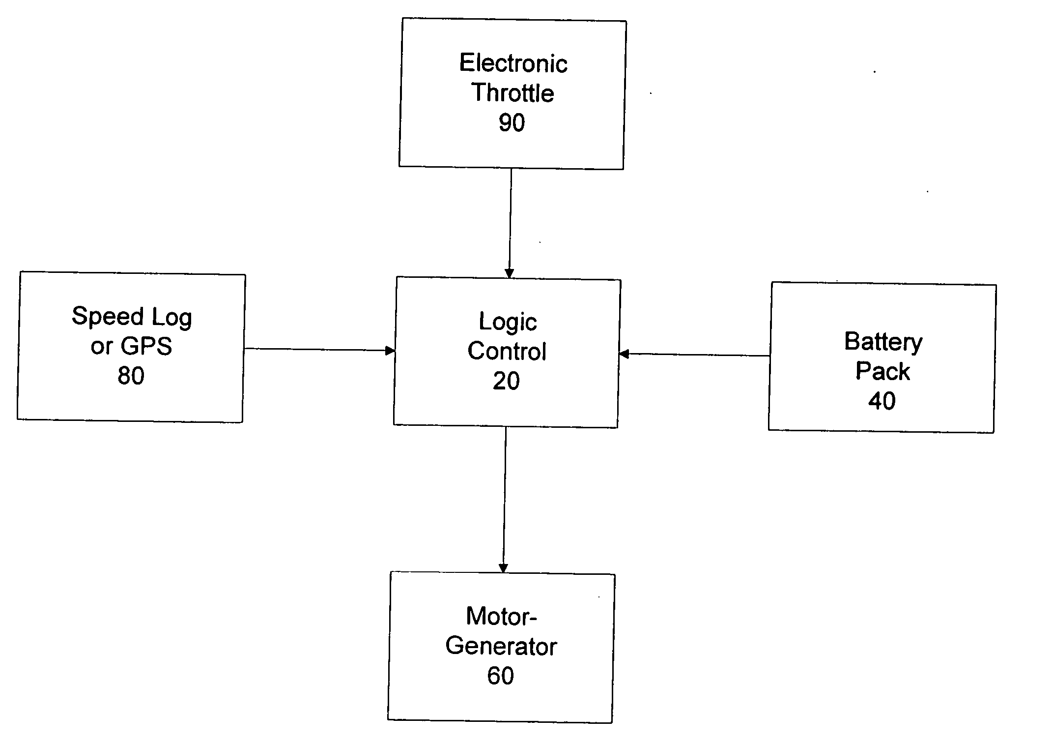
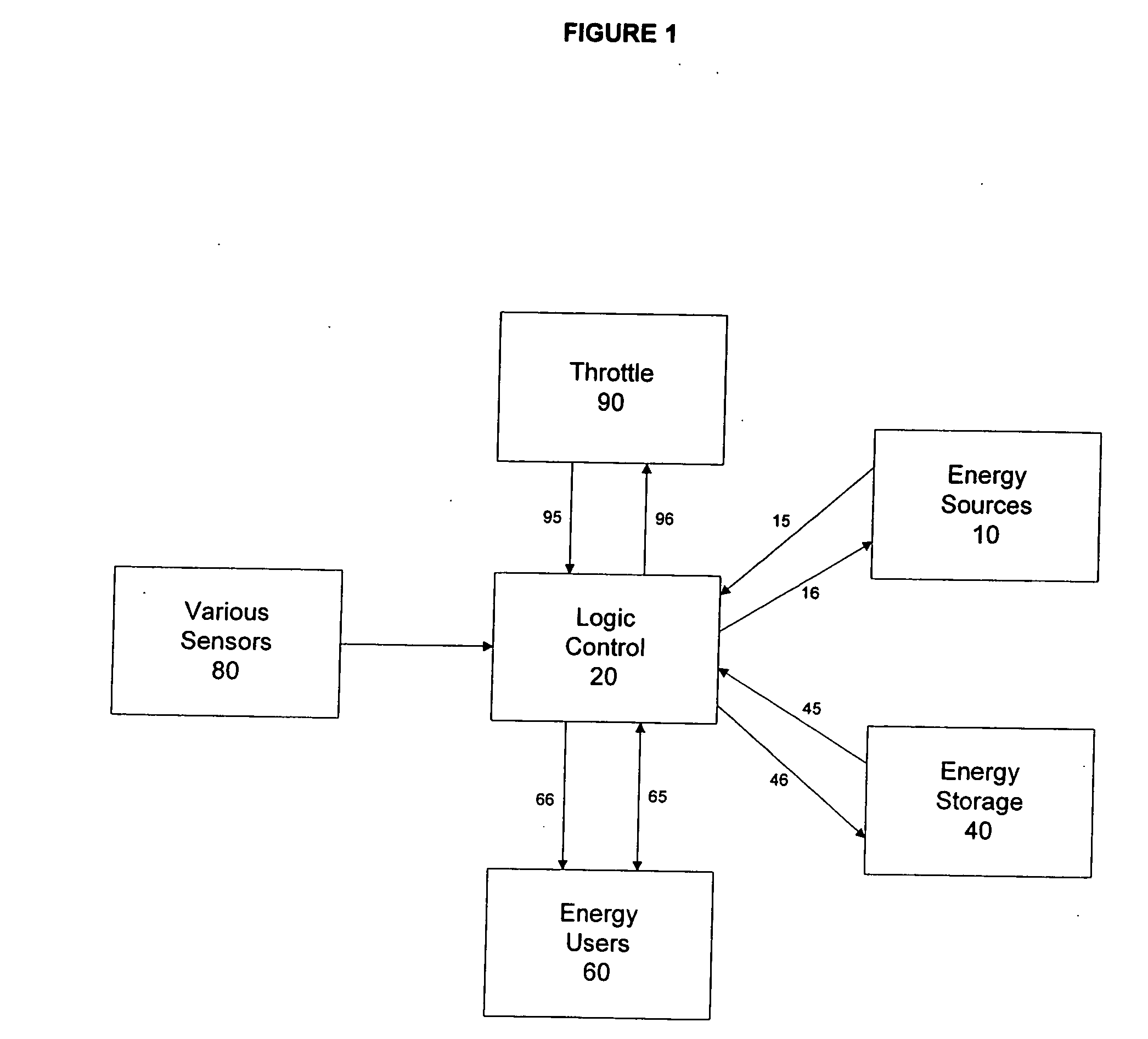
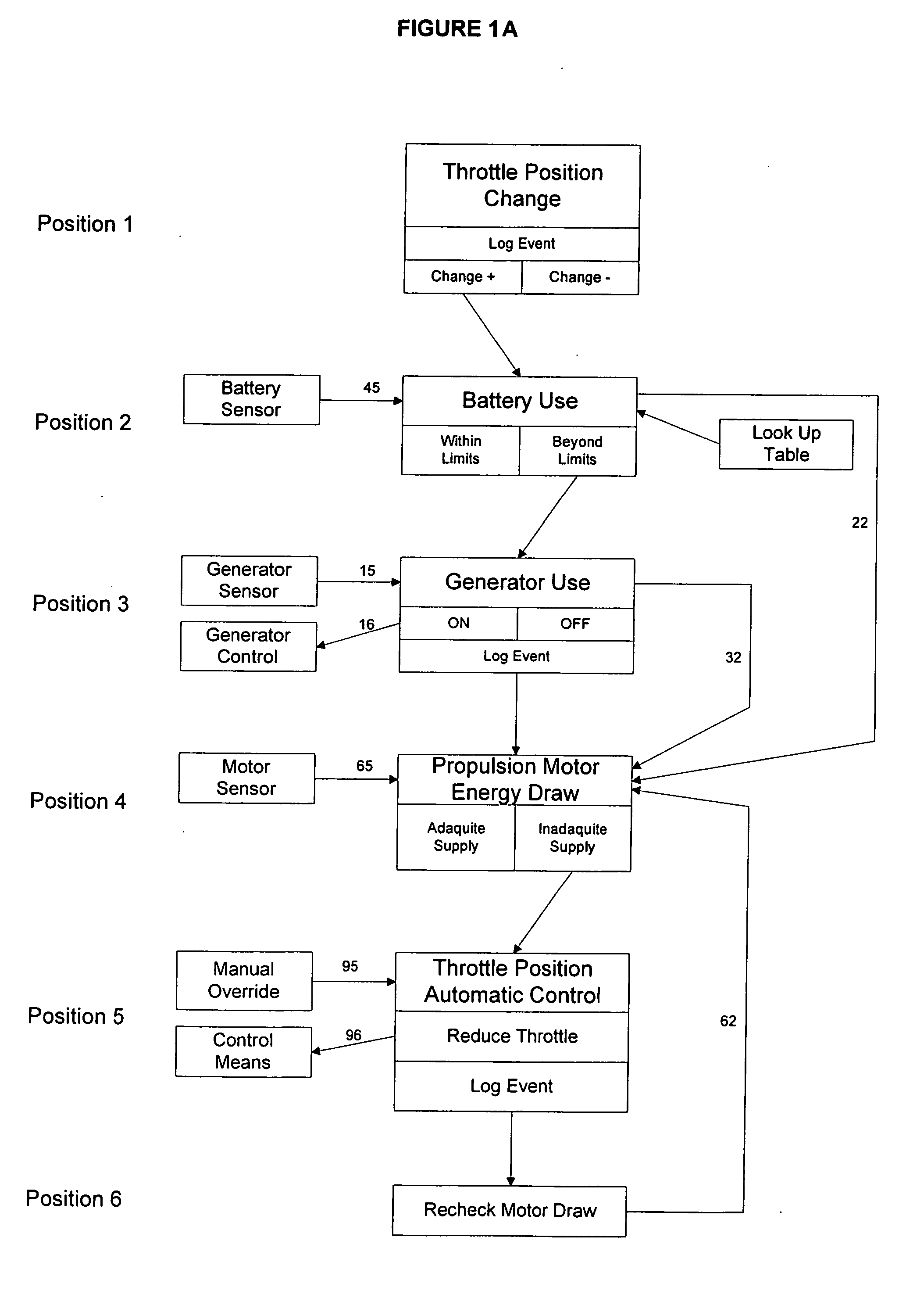
[0006] The present invention includes methods, systems, and algorithms for an autonomous energy generating and energy using system that can enhance system monitoring, control, maintenance, efficiency, and safety. In one embodiment one or more energy sources are utilized along with one or more energy storage devices, all of these can be monitored and controlled by a logic control function which senses both system-internal and external conditions to provide for various desirable functions. The various system components can be arranged and connected in such a way that the logic control function can consider overall system condition and health and provide for a desirable system maintenance regiment while also providing for a means of logging periodic and special events.

Problems solved by technology

Despite these advances, there are still no successful applications of vehicle / vessel autonomous position and attitude control to power generation / use management systems.
As power consumption and systems health on autonomous vehicles / vessels containing complex multi-source / multi-use systems is of high concern, integrating health management and automatic systems control for the power management into the basic system becomes more important, but much of the prior art addresses only individual component control while little is successfully accomplished for control of the total system or to account for unique and special conditions that can exist in such total systems.

Method used


Image

  • System and method for automating power generation, propulsion and use management
  • System and method for automating power generation, propulsion and use management
  • System and method for automating power generation, propulsion and use management

Examples


Embodiment Construction

[0026] This invention, among other objectives that are explained throughout this description, advances and improves upon PCT Patent Application Publication No. WO 2005 / 075234, entitled “Regenerative Motor Propulsion Systems” (incorporated herein by reference), focusing on greatly automating the system. That patent and this present invention primarily use examples of marine applications, but the skilled artisan can readily apply this technology to far more application. A few of the possible applications are listed, but are not limited to; water craft, land-based vehicles, aircraft, elevators, conveyors, heating and air conditioning equipment, pumps, machine tools, and space craft propulsion and inertial stabilization. One embodiment of this invention is presented in the attached figures. These depict an application of the invention to a marine sailing vessel.

[0027] One illustrative embodiment of a system of the invention is shown in FIG. 1. This figure depicts various Energy Sources...


PUM


Abstract

An automated energy generating and energy using system is provided. The system includes at least one electric energy user, at least one electric energy source, and may also include at least one electric energy storage element. These elements are instrumented so that each electric energy user has a sensor for determining an amount of energy used, each electric energy source has a sensor for determining an amount of energy provided, and electric energy storage element has a sensor for determining an amount of energy available in the storage element. A controller is operatively connected to each energy source, energy storage element and sensor. The controller is configured to control a level of operation of the at least one source of energy based upon at least the amount of energy used and the amount of energy available in the storage element, if employed. In this way, an automated electrical energy system is provided.

Description

CROSS REFERENCE TO RELATED APPLICATION [0001] This claims priority to U.S. Provisional Patent Application No. 60 / 660,659, filed on Mar. 11, 2005, and entitled “System for Automation for Power Generation, Propulsion and Use Management,” which application is incorporated herein by reference in its entirety.FIELD OF THE INVENTION [0002] The invention relates generally to control of self-contained, autonomous energy producing and using systems and more specifically to the monitoring of system conditions and health and the automatic control and adjustment of component parameters to maintain proper energy levels and system health while providing for safety of the operation of such systems and provides a means to log events and periodically log conditions. BACKGROUND OF THE INVENTION [0003] As mechanized systems, including propulsion systems, have become more sophisticated, logic controls have been employed to monitor and automatically adjust functions of such systems in order to better ma...

Claims


Application Information

Patent Timeline
IPC IPC(8): B60L1/00B60K6/46
CPCB60K6/105Y02T90/121B60K6/46B60K6/48B60L8/003B60L8/006B60L11/123B60L11/1842B60L11/1861B60L2240/36B60L2240/622B60L2250/16B60W10/06B60W10/08B60W10/26B60W20/00B60W2510/244B60W2520/10B60W2530/14B60W2540/10B60W2540/30B60W2710/0605Y02T10/6204Y02T10/6217Y02T10/6221Y02T10/6286Y02T10/7005Y02T10/705Y02T10/7077Y02T10/7083Y02T10/7094Y02T10/7291Y02T90/128Y02T90/14Y02T90/16Y02T90/162Y02T90/163Y02T10/7044Y04S10/126Y02E60/721B60K6/20Y02T10/7072B60L50/61B60L55/00B60L58/12Y02E60/00Y02T10/62Y02T10/70Y02T10/72B60W2556/10B60W20/10B60W10/24Y02T90/12
Inventor CHRISTIAN, ANDREW J.PESIRIDIS, R. ALEX
Owner TECHNIPOWER SYST INC
Learn More