[0011] The present invention has been made in view of the above circumstances and has an object to provide a reverse-shift-activated mirror angle control method and apparatus for a vehicle outer mirror which method and apparatus can prevent miscounting of pulses generated by switching of brushes and reduce deviations in return position caused by repetition of turning operation. Also, the present invention has an object to provide a rotation amount detection method and apparatus which can improve accuracy of detecting a rotation amount of a DC brush motor running in
steady state operation, where the rotation amount is detected by counting pulses generated by switching of the brushes when the DC brush motor rotates.
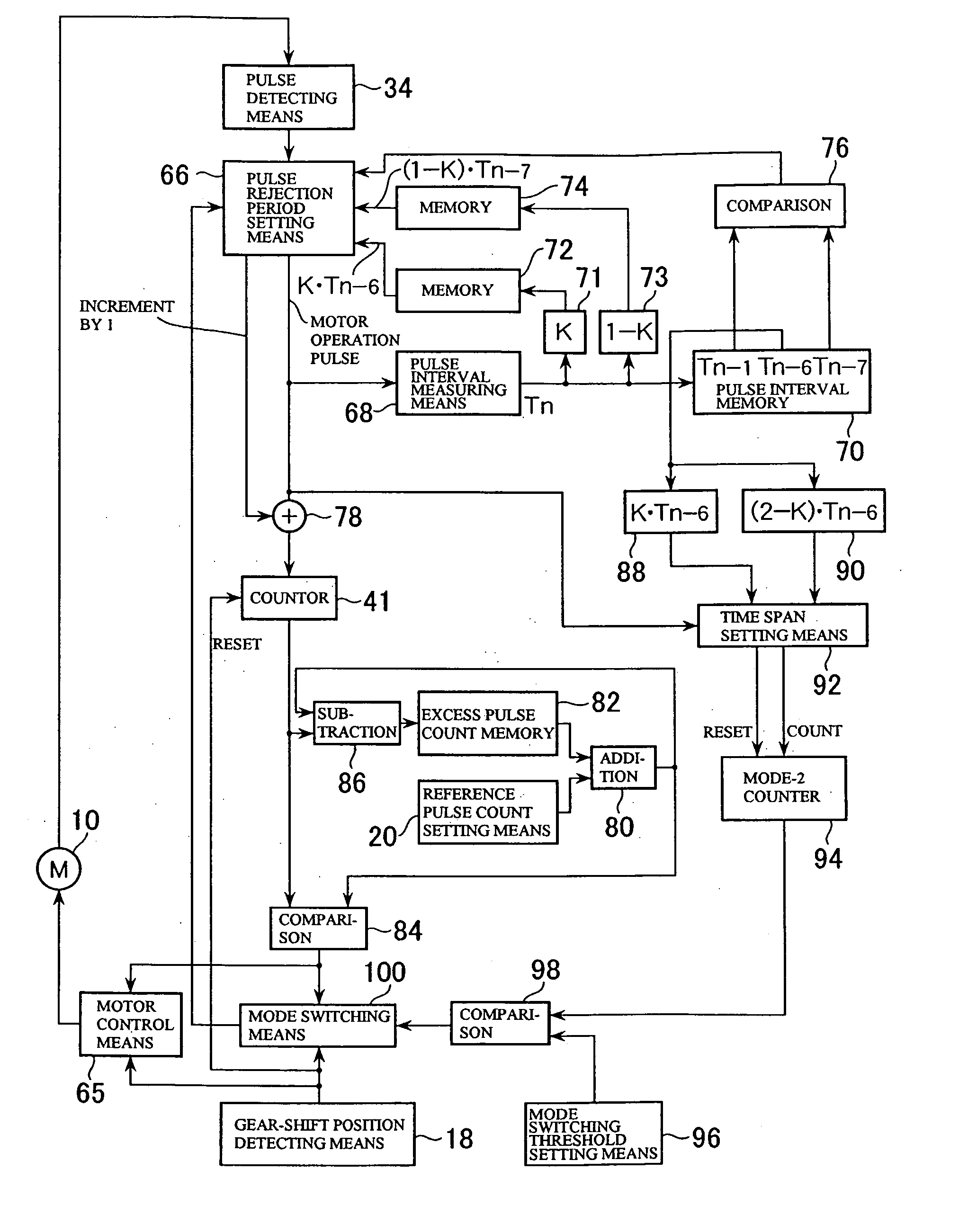
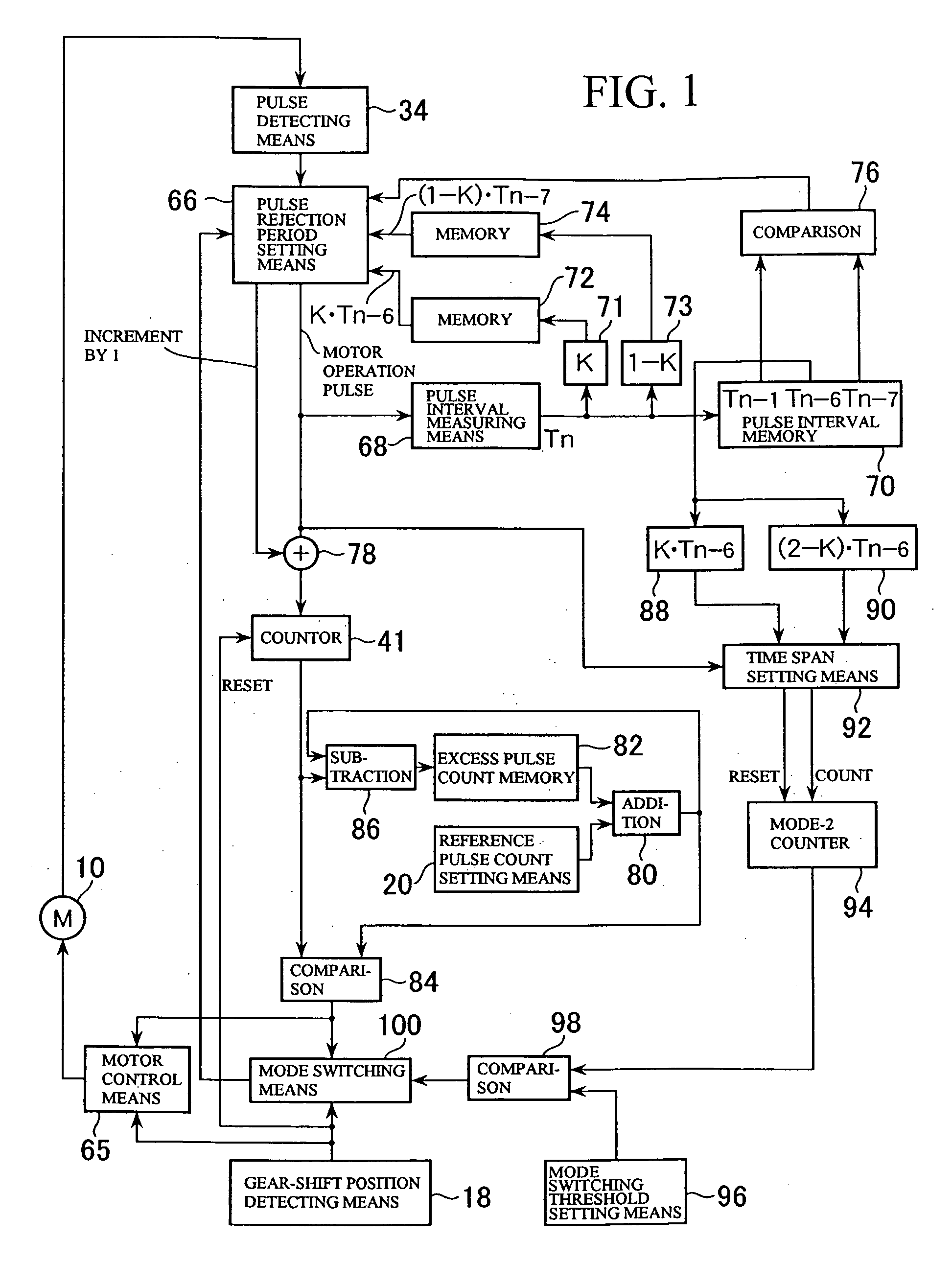
[0015] Thus, in the reverse-shift-activated mirror angle control method according to the present invention, the pulse rejection period during steady-state operation of the DC brush motor is ended when a predetermined time elapses from a start point of the pulse rejection period, where the predetermined time is calculated by multiplying a pulse interval of a corresponding pulse zone one rotation before a pulse zone to which the pulse rejection period belongs by a coefficient K(½<K<1). That is, according to this method, even if there are variations in pulse intervals between adjacent pulses during steady-state operation due to
assembly errors of the motor and the like, the variations do not have effect because the end time of each pulse rejection period is set based on the pulse interval at the corresponding position (the same rotational position) in the previous rotation. Thus, this method can reduce miscounting due to noise pulses or missing pulses and consequently reduce deviations in return position caused by repetition of turning operation. Besides, unlike the technique described in
patent document 1, since there is no need to use a hardware-based
high pass filter or
low pass filter, this method can avoid cost increases due to addition of hardware.
[0019] Also, in the reverse-shift-activated mirror angle control method according to the present invention, the pulse count can be forcibly incremented by one if a next pulse is not generated from the end point of a pulse rejection period to a predetermined time point in a pulse zone next to the pulse zone to which the pulse rejection period belongs. This makes it possible to prevent miscounting due to missing pulses. In this case, the predetermined time point may be, for example, a time point when a predetermined time elapses from the end point of the pulse rejection period, where the predetermined time is calculated as the sum of a time obtained by multiplying the pulse interval of a corresponding pulse zone one rotation before the pulse zone to which the pulse rejection period belongs by the coefficient 1−K and a time obtained by multiplying the pulse interval of the pulse zone next to the corresponding pulse zone one rotation before by the coefficient K. Besides, if a pulse interval is not measured in a pulse zone because no pulse is generated until the predetermined time point, for example, the last pulse intervals measured at corresponding pulse zones in a rotation preceding the pulse zone in which no pulse is generated may be used as pulse interval values which define end points of pulse rejection periods in corresponding pulse zones one rotation after two pulse zones before and after the pulse zone.
[0026] With the DC brush motor rotation amount detection method according to the present invention, even if there are variations in pulse intervals between adjacent pulses during steady-state operation due to
assembly errors of the motor and the like, variations do not have effect because the end time of each pulse rejection period is set based on the pulse interval at the corresponding position (the same rotational position) in the previous rotation. Thus, this method can reduce miscounting due to noise pulses or missing pulses and consequently improve accuracy of detecting a rotation amount of a DC brush motor running in
steady state operation.
[0030] Also, in the DC brush motor rotation amount detection method according to the present invention, the pulse count can be forcibly incremented by one if a next pulse is not generated from the end point of a pulse rejection period to a predetermined time point in a pulse zone next to the pulse zone to which the pulse rejection period belongs. This makes it possible to prevent miscounting due to missing pulses. In this case, the predetermined time point may be, for example, a time point when a predetermined time elapses from the end point of the pulse rejection period, where the predetermined time is calculated as the sum of a time obtained by multiplying the pulse interval of a corresponding pulse zone one rotation before the pulse zone to which the pulse rejection period belongs by the coefficient 1−K and a time obtained by multiplying the pulse interval of the pulse zone next to the corresponding pulse zone one rotation before by the coefficient K. Besides, if a pulse interval is not measured in a pulse zone because no pulse is generated until the predetermined time point, for example, the last pulse intervals measured at corresponding pulse zones in a rotation preceding the pulse zone in which no pulse is generated may be used as pulse interval values which define end points of pulse rejection periods in corresponding pulse zones one rotation after two pulse zones before and after the pulse zone.

