Transferred-impedance filtering in RF receivers

a technology of transmitting impedance filtering and receiver, which is applied in the field of communication systems, can solve the problems of large pwbs, high cost of components, and inability to integrate with a standard cmos or bicmos process

Active Publication Date: 2006-09-21
NOKIA TECHNOLOGLES OY
View PDF5 Cites 22 Cited by
  • Summary
  • Abstract
  • Description
  • Claims
  • Application Information

AI Technical Summary

Benefits of technology

[0025] There will be no need for expensive external filtering;
[0026] Modular

Problems solved by technology

These components are expensive, impossible to integrate with a standard CMOS or BiCMOS process and also require large areas of PWBs (printed wiring boards).
Such filters also d

Method used


Image

  • Transferred-impedance filtering in RF receivers
  • Transferred-impedance filtering in RF receivers
  • Transferred-impedance filtering in RF receivers

Examples


Embodiment Construction

[0035] The present invention provides a method for using transferred-impedance filtering in RF (radio frequency) receivers (e.g., inside of a mobile communication deice), wherein said filtering can be done with MOS-switches transferring impedance of a regular RC or RCL circuit to RF frequency filtering inside an RFIC (radio frequency integrated circuit).

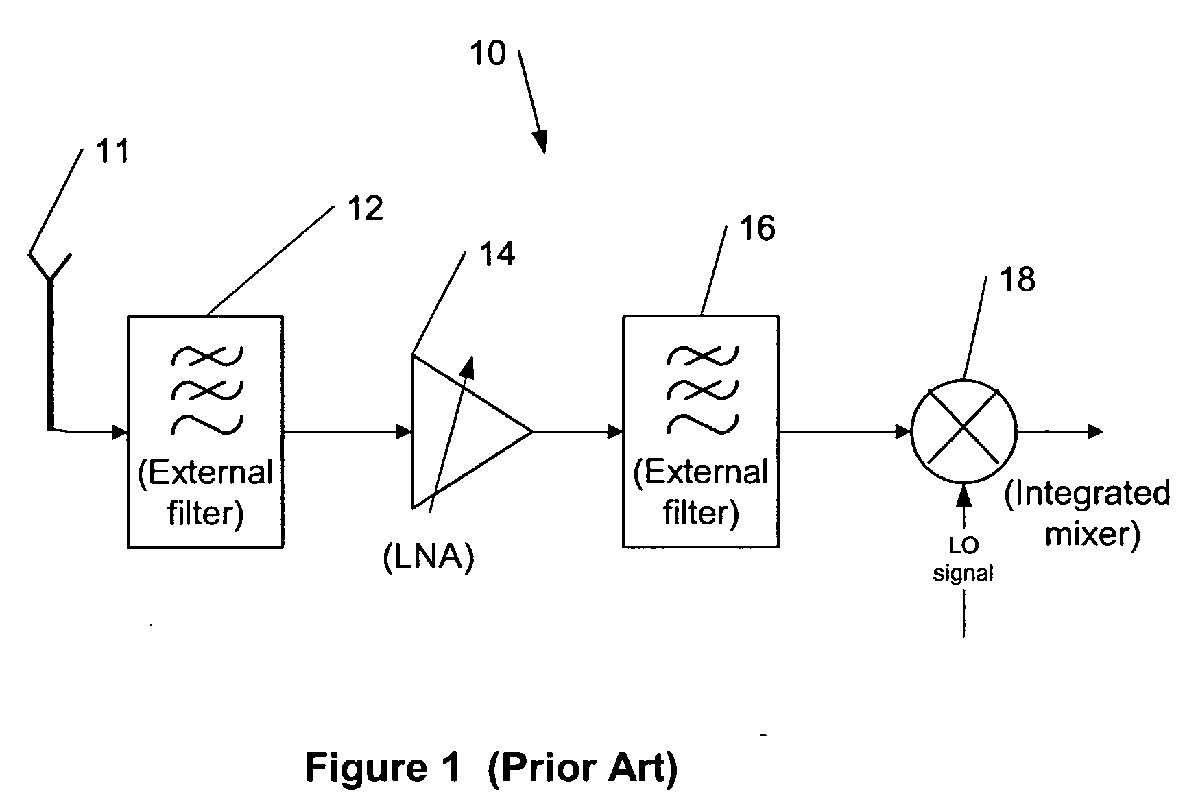
[0036]FIG. 1 shows an example of a block diagram of a front end of an RF receiver 10, according to the prior art. An antenna 11 receives a radio frequency signal and converts it to an electrical domain. Then the signal is filtered first using an external filter 12, amplified using a low noise amplifier (LNA) 14 and filtered again using an external filter 16 before it is provided to a mixer 18 as a part of a normal algorithm, according to the prior art.

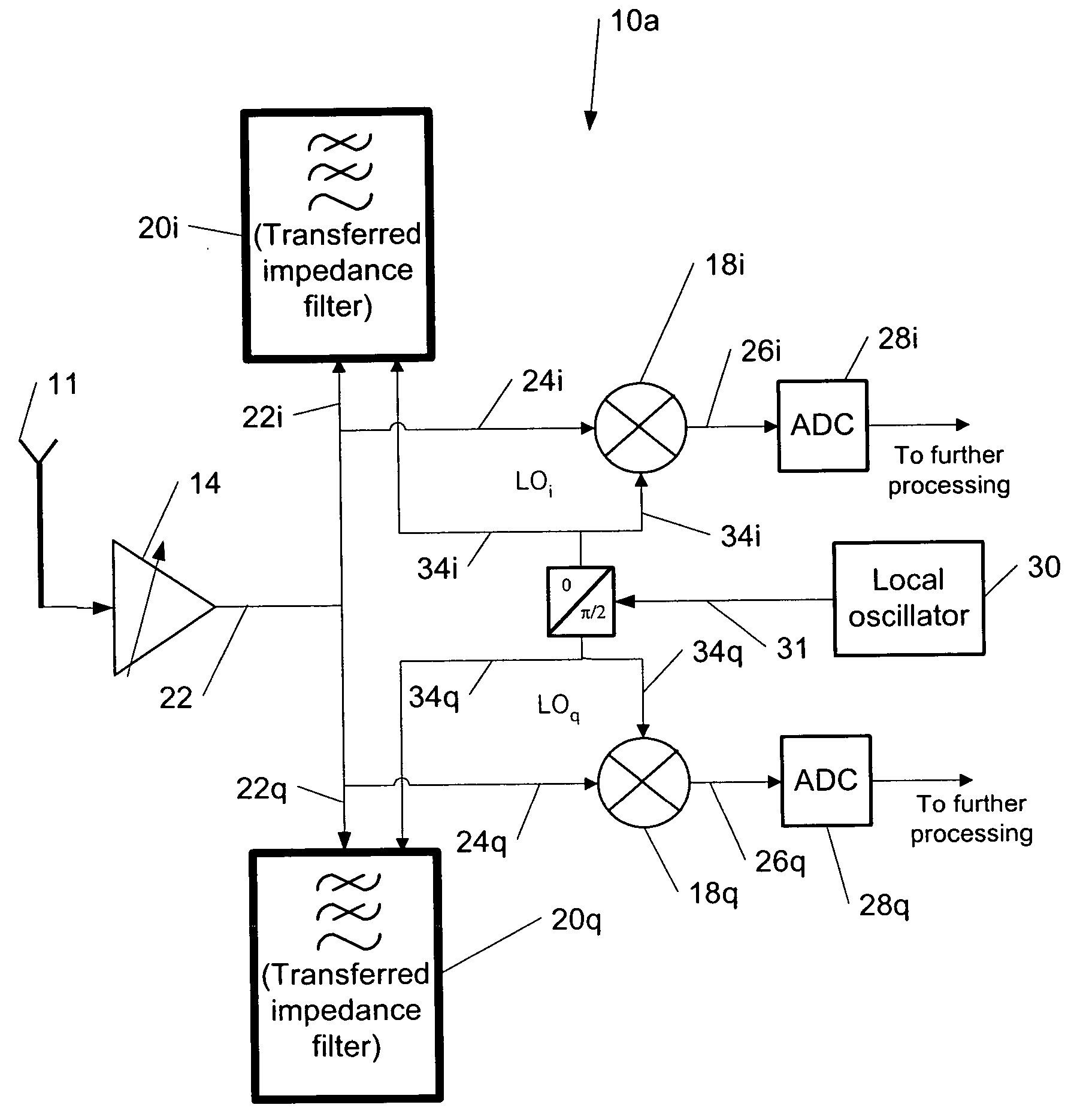
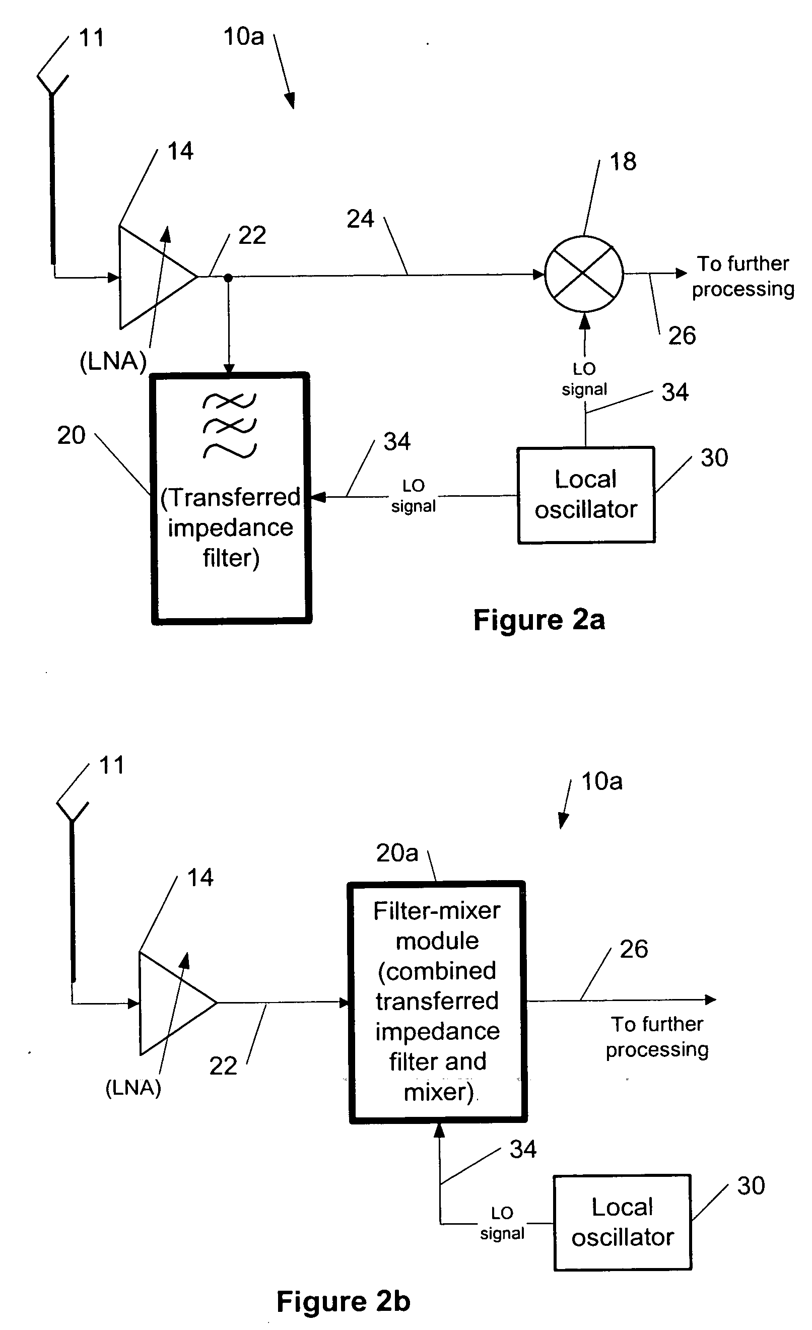
[0037]FIGS. 2a and 2b show examples among others of block diagrams of a front end of RF receivers 10a and 10b, respectively, according to the present invention. Compared to the prior ...


PUM


Abstract

The present invention provides a method for using transferred-impedance filtering in RF (radio frequency) receivers (e.g., inside of a mobile communication device), wherein said filtering can be done with MOS-switches transferring impedance of a regular RC or RCL circuit to RF frequency filtering inside an RFIC (radio frequency integrated circuit).

Description

TECHNICAL FIELD [0001] This invention generally relates to communication systems, and more specifically to using transferred-impedance filtering in RF receivers. BACKGROUND ART [0002] The RF receivers must tolerate high blocking signals while maintaining their own performance. This requires filtering for RF-signals prior to a LNA (low noise amplifier) and in many systems also after the LNA. This is especially true in code division multiple access systems (e.g., CDMA2000 and WCDMA) where a transmitter usually sends its high-level signal while a receiver receives a very low-level signal. [0003] At the present time, filtering is done mainly with SAW (surface acoustic wave) or BAW (bulk acoustic wave) filters or resonators. These components are expensive, impossible to integrate with a standard CMOS or BiCMOS process and also require large areas of PWBs (printed wiring boards). Such filters also decrease the possibility for modularity and also increase the number of I / O's (inputs / output...

Claims


Application Information

Patent Timeline
IPC IPC(8): H04B1/10
CPCH03H19/008H04B1/0017H04B1/18H03K5/00H04B1/10H04B1/40
Inventor VILHONEN, SAMI
Owner NOKIA TECHNOLOGLES OY
Why Eureka
Try Eureka