Light-emitting device and apparatus having the same

a technology of light-emitting devices and apparatuses, applied in lighting and heating apparatus, planar/plate-like light guides, instruments, etc., can solve the problems of large illumination apparatus, inability to provide adequate characteristics of illumination light, and inability to realize favorable exposure, etc., and achieve the effect of small siz

Inactive Publication Date: 2006-09-21
CANON KK
View PDF7 Cites 36 Cited by
  • Summary
  • Abstract
  • Description
  • Claims
  • Application Information

AI Technical Summary

Benefits of technology

[0011] It is an object of the present invention to provide a light-emitting device which allows efficient irradiation of light from a plurality of light sources to achieve a predetermined light-emission characteristic (for example, a light distribution characteristic) and also has a small size.

Problems solved by technology

If the conventional illumination apparatus is used under the situation, illumination light having adequate characteristics cannot be provided especially in taking images at an extremely close range (macro photography).
Specifically, part of the illumination light is blocked by an image-taking lens barrel to prevent uniform illumination all over the necessary irradiation area, and the extremely short distance to an object causes overexposure of the object to result in a failure to realize favorable exposure.
However, such an illumination apparatus tends to be large and expensive.
In this manner, it has conventionally been difficult for a small illumination apparatus to perform illumination appropriate for both of ordinary image-taking and macro photography.
However, as shown in Japanese Patent Laid-Open No. 2000-89318, a sufficient light amount for taking images is difficult to provide unless a plurality of LEDs are used.
In other words, no proposal has been made conventionally of an illumination apparatus which allows efficient irradiation of light from a plurality of LEDs to realize an illumination (light distribution) characteristic suitable for macro photography and also has a small size.

Method used


Image

  • Light-emitting device and apparatus having the same
  • Light-emitting device and apparatus having the same
  • Light-emitting device and apparatus having the same

Examples


embodiment 1

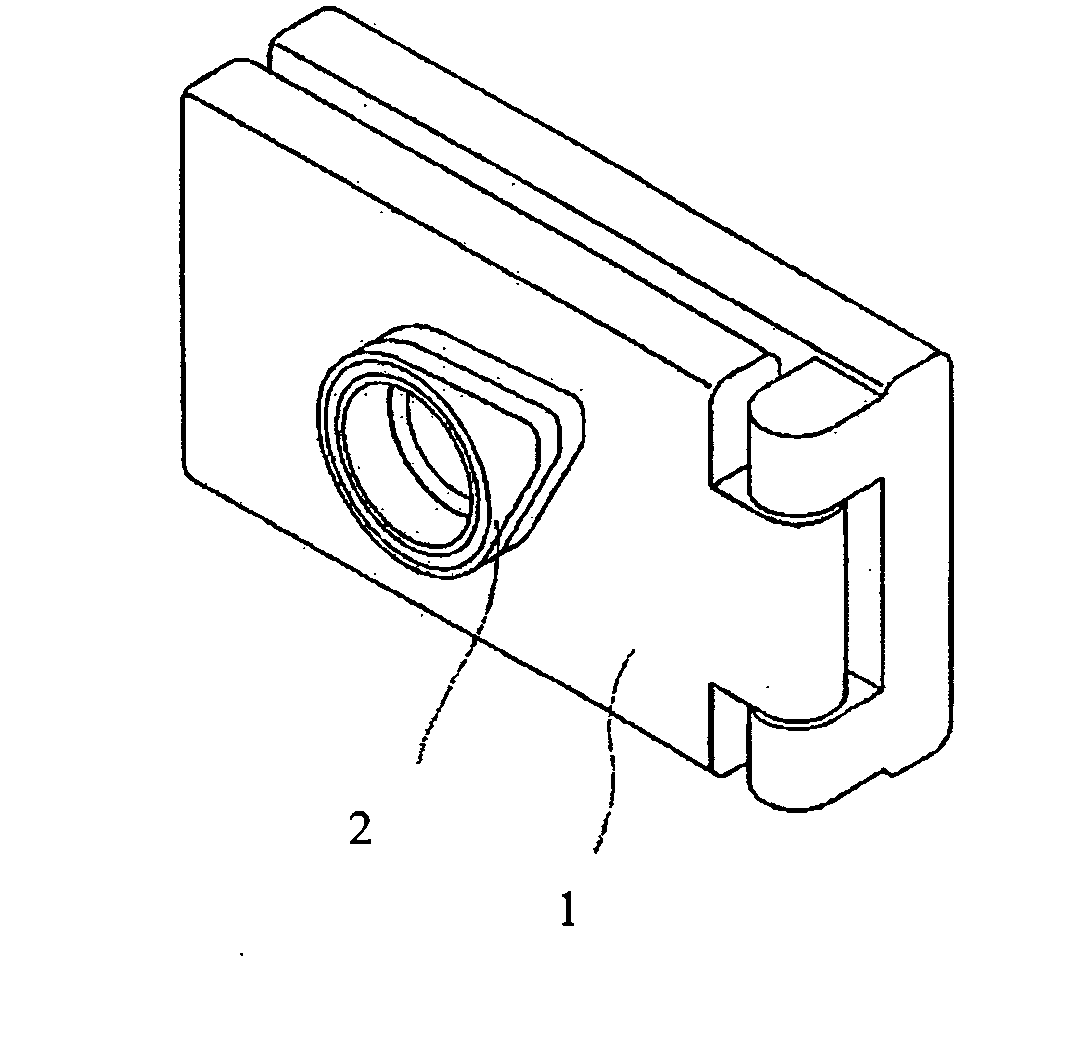
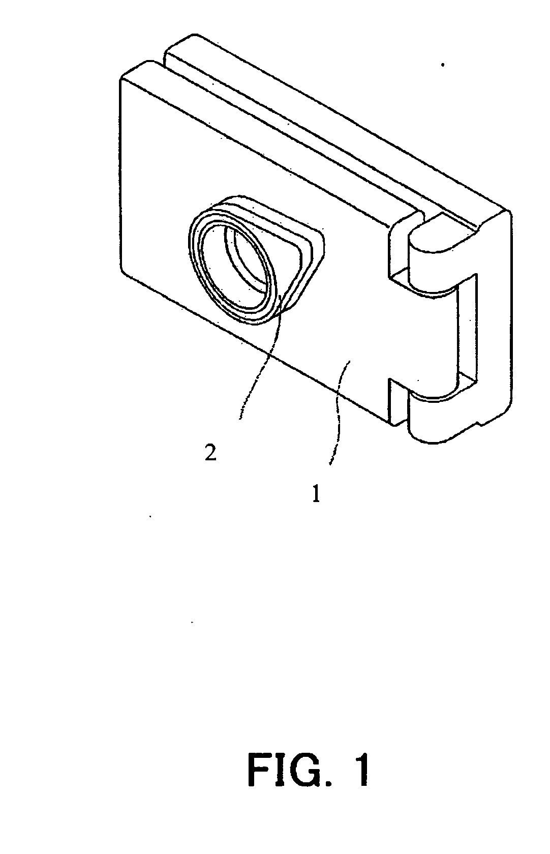
[0033] FIGS. 1 to 3 show a ring light for macro photography serving as a light-emitting device which is Embodiment 1 of the present invention. The ring light for macro photography of Embodiment 1 is mounted on a camera-equipped cellular phone as an example of an apparatus.

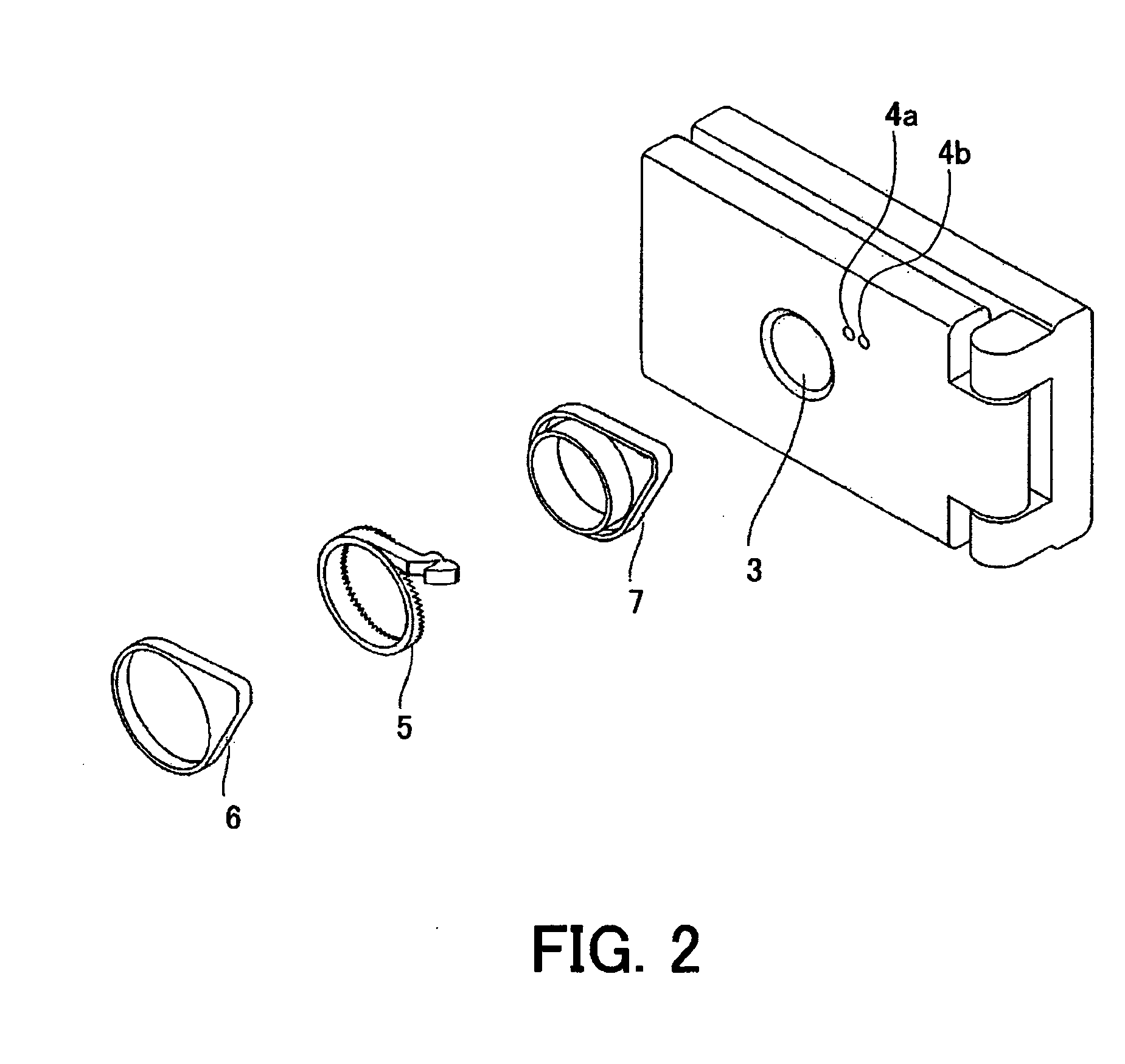
[0034]FIG. 1 is a perspective view of the camera-equipped cellular phone on which the ring light for macro photography is mounted. FIG. 2 is an exploded perspective view showing the ring light for macro photography. FIG. 3 is a perspective view showing the principal structure of an optical system of the ring light for macro photography.

[0035] In FIGS. 1 to 3, reference numeral 1 shows the camera-equipped cellular phone which has a communication function and a camera function. Reference numeral 2 shows the ring light for macro photography which is used to illuminate an object in taking an image at a close range (macro photography). The ring light 2 for macro photography is removably mounted on the camera-equipped ...

embodiment 2

[0061] FIGS. 8 to 10 show a light-emitting device which is Embodiment 2 of the present invention. In Embodiment 2, components identical to those in Embodiment 1 are designated with the same reference numerals and description thereof is omitted. Embodiment 1 has been described in conjunction with the case where the optical member has the ring-shaped emergence surface. In Embodiment 2, an optical member has a plane emergence surface to change a luminous flux from an LED as a point source of light into a luminous flux which looks as if it is emitted from a surface light source. The light-emitting device of Embodiment 2 can be used for various purposes such as illumination for image-taking, backlight of a liquid crystal display, and a display by blinking or lighting in an electronic device such as a cellular phone.

[0062] Since light ray tracing diagrams of luminous fluxes emitted from LEDs are similar to those in Embodiment 1, they are omitted in Embodiment 2.

[0063]FIG. 8 shows an exa...

embodiment 3

[0069]FIG. 11 shows an electronic camera (digital still camera or video camera) serving as an image-taking apparatus on which a ring light for macro photography which is Embodiment 3 of the present invention is mounted. FIG. 12 is an exploded view showing the ring light for macro photography mounted on the electronic camera. FIG. 13 shows the principal structure of an optical system of the ring light for macro photography mounted on the electronic camera. In Embodiment 3, components identical to those in Embodiment 1 are designated with the same reference numerals and description thereof is omitted. While Embodiment 1 has been described in conjunction with the two entrance portions provided for the optical member, three entrance portions are provided for an optical member in Embodiment 3. This allows a larger amount of luminous flux from an LED to emerge toward an object.

[0070] In FIGS. 11 and 12, reference numeral 12 shows the electronic camera. Reference numeral 13 shows the ring...


PUM


Abstract

A light-emitting device is disclosed which allows efficient irradiation of light from a plurality of light sources to achieve a predetermined light emission characteristic and has a small size. The light-emitting device has an optical member which includes a first reflecting surface which reflects light incident thereon from a first light source, a second reflecting surface which reflects light incident thereon from a second light source, and an emergence portion which causes the light from the first reflecting surface and the light form the second reflecting surface to emerge therefrom. The optical member reflects the light by the second reflecting surface and then transmits the light through the first reflecting surface to guide the light to the emergence portion.

Description

BACKGROUND OF THE INVENTION [0001] The present invention relates to a light-emitting device for use in various apparatuses such as image-taking apparatuses including a digital still camera and a video camera, and a camera-equipped cellular phone. [0002] A typical illumination apparatus (light-emitting device) used in a camera is a flash unit which provides a large amount of illumination light by light emission in a flash discharge tube. In recent years, however, the large amount of illumination light, which has conventionally been used, is not necessarily required due to the increased sensitivity of an image-pickup device employing a CCD (charge-coupled device) sensor and a CMOS (complementary metal oxide semiconductor) sensor in an electronic camera. On the other hand, light-emitting diodes (hereinafter abbreviated as “LEDs”) have been improved in luminance and widely used for various types of illumination. [0003] Thus, an illumination apparatus for taking images by using the LED a...

Claims


Application Information

Patent Timeline
Patent Type & Authority Applications(United States)
IPC IPC(8): G02B27/10
CPCG02B6/0018G02B6/002G02B6/003G02B6/0038G02B6/0068G02B17/0856G02B17/086G03B15/03G03B2215/0539
Inventor KOJIMA, NOBUHISA
Owner CANON KK
Why Eureka
Try Eureka