
Video recording system, video camera, video recording apparatus, method of controlling video recording apparatus by video camera, and method of recording video signal in video recording

a video recording and video recording technology, applied in the field of video recording systems, video recording apparatuses, video recording methods, and methods of recording video signals in video recording, can solve problems such as difficult work, increase in work on the side of managing stations, and deterioration of system reliability, so as to improve the reliability of the control information supplied by the video camera to the video recording apparatus

Active Publication Date: 2006-09-21
SONY CORP
View PDF17 Cites 20 Cited by
  • Summary
  • Abstract
  • Description
  • Claims
  • Application Information

AI Technical Summary

Benefits of technology

The present invention is a video recording system that improves the reliability of control information to record / stop recording and addresses the problems of a pool coverage system. The system includes a video camera and a video recording apparatus, and control information is generated on the side of the video camera at predetermined intervals in accordance with the operational status of the operation unit. The control information is transmitted to the video recording apparatus as a serial digital signal and separated from the video signal. The video recording apparatus controls the recording system based on the control information. The technical effects of the invention include enhanced reliability of control information, improved recording reliability, and simplified operation for setting equipment for coverage.

Problems solved by technology

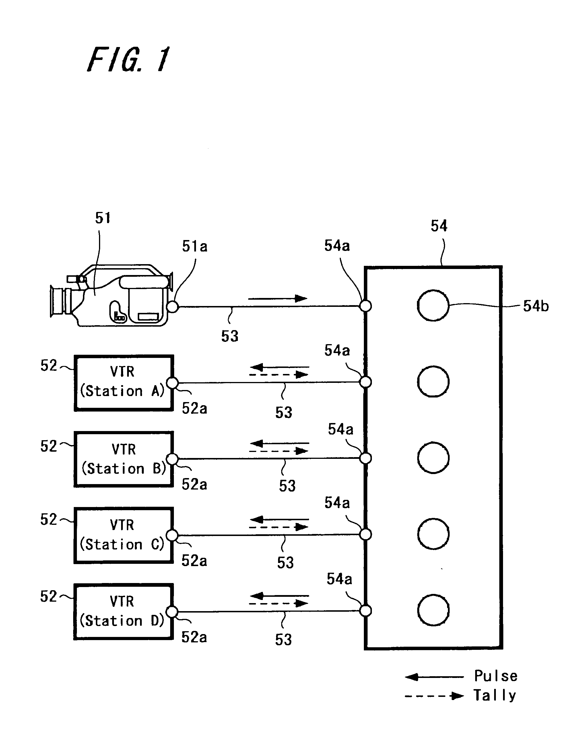
Hence, reliability of the system deteriorates due to a cause on the side that supplies to the VTR 52 control information (pulse) to record / stop recording.
However, work on the side of managing station increases if such checking is required.
Due to this reason, when a space for setting equipment for coverage is small as the above-described space in a baseball stadium, it is difficult to work when replacing a video tape of each VTR 52 and the like, because all of the plurality of VTRs 52 need to be set in the narrow space.

Method used


Image

  • Video recording system, video camera, video recording apparatus, method of controlling video recording apparatus by video camera, and method of recording video signal in video recording
  • Video recording system, video camera, video recording apparatus, method of controlling video recording apparatus by video camera, and method of recording video signal in video recording
  • Video recording system, video camera, video recording apparatus, method of controlling video recording apparatus by video camera, and method of recording video signal in video recording

Examples


Embodiment Construction

[0059] Hereinafter, an embodiment of the present invention is specifically explained using the accompanied drawings. In the followings, an example in which an embodiment of the present invention is applied to perform pool coverage is explained.

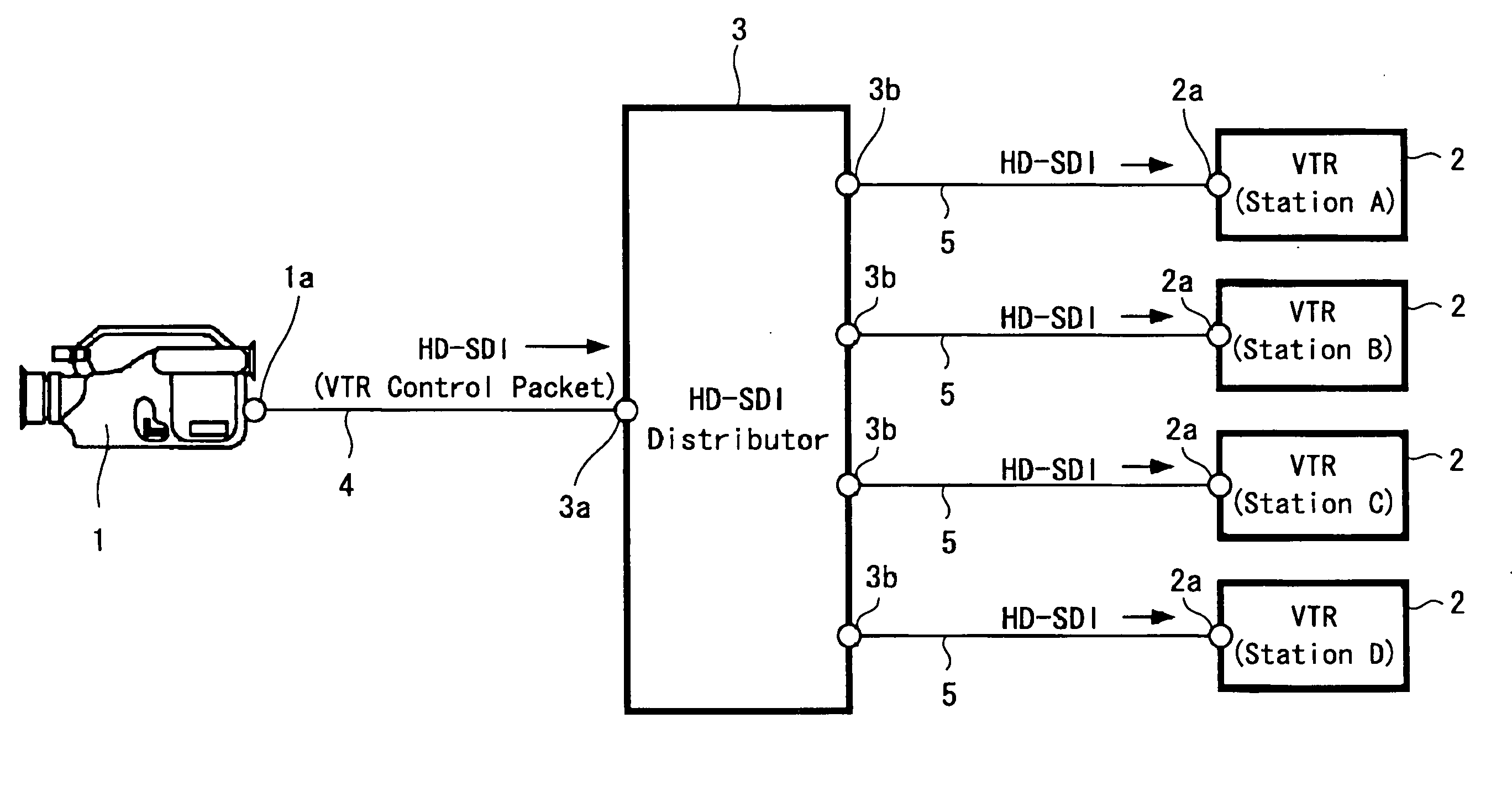
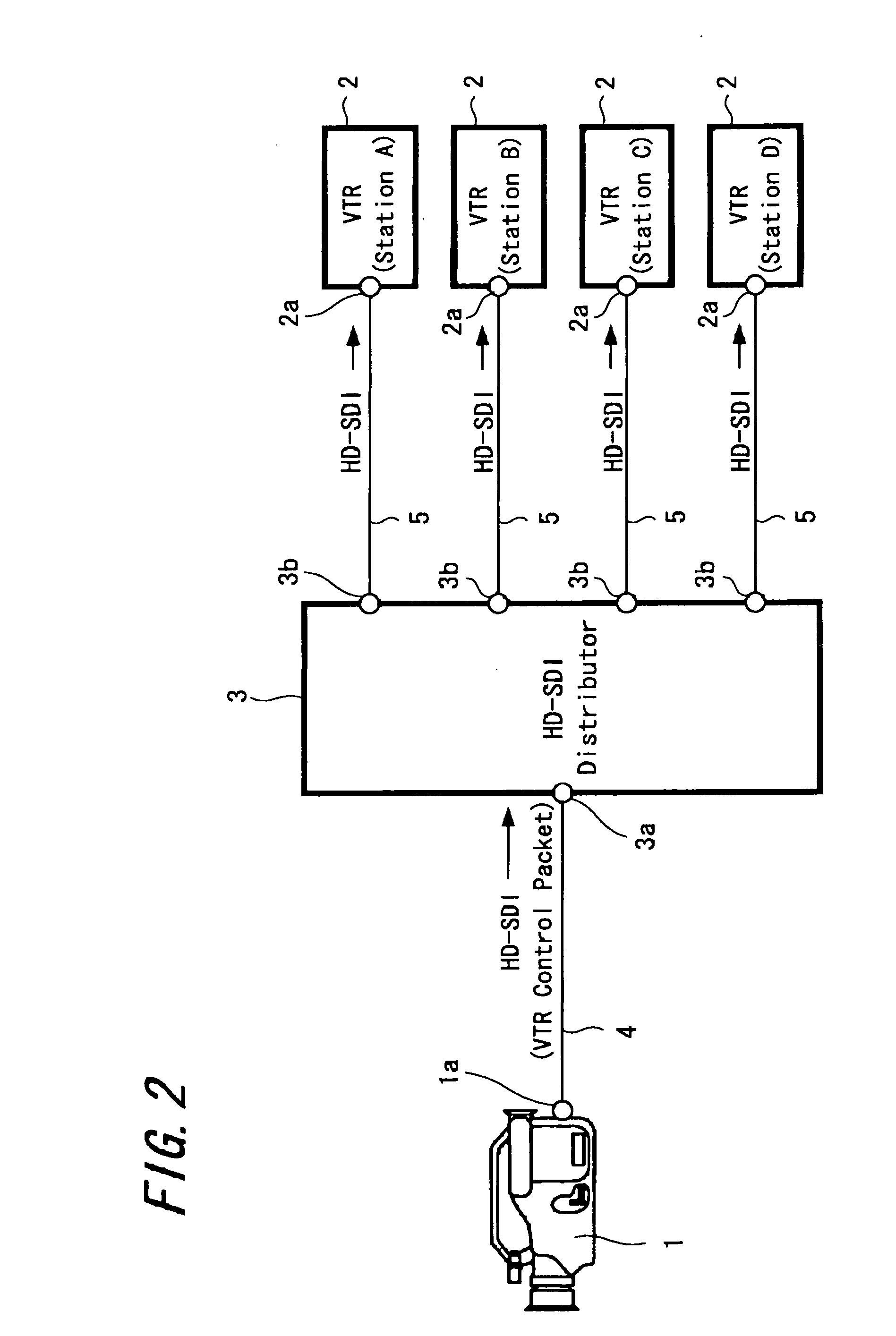
[0060]FIG. 2 is a diagram showing the whole configuration of a system for pool coverage to which an embodiment of the present invention is applied. A video camera 1 is a VTR-incorporated video camera which supports a digital HD and has a HD-SDI output terminal 1a and which is brought into the scene of coverage by a camera operator of a managing station.

[0061] The HD-SDI output terminal 1a of the video camera 1 is connected to a HD serial digital input terminal 3a of a HD-SDI distributor 3 using a BNC cable 4.

[0062] Each of VTRs 2 is a VTR having a HD serial digital input terminal 2a and is prepared by each of broadcasting stations A to D other than the managing station. The HD serial digital input terminal 2a of each VTR 2 is connected to o...


PUM


Abstract

A video recording system is provided in which reliability of information supplied from a video camera to control recording and the like is improved when video being obtained by a video camera is recorded in one or more VTRs. In the video recording system, the video camera multiplexes: control information to control the VTR in accordance with an operational status of an operation unit of the video camera and a video signal from an imaging unit of the video camera, and transmits the result to the VTR as a transmission serial digital signal. The VTR separates the video signal and the control information from the serial digital signal and controls a video recording system of the VTR based on the control information.

Description

CROSS REFERENCES TO RELATED APPLICATIONS [0001] The present invention contains subject matter related to Japanese Patent Application JP 2005-077965 filed in the Japanese Patent Office on Mar. 17, 2005, the entire contents of which being incorporated herein by reference. BACKGROUND OF THE INVENTION [0002] 1Field of the Invention: [0003] The present invention relates to a video recording system including a video camera and a video recording apparatus remotely controlled by the video camera, and particularly to the system in which a malfunction of the video recording apparatus is prevented. [0004] 2Description of the Related Art: [0005] In the case where a plurality of broadcasting stations have coverage on the same scene, there is one mode of the coverage called “pool coverage”. This is such a mode that one broadcasting station among the plurality of broadcasting stations is appointed as a managing station, a camera operator of the managing station brings a video camera into the scene...

Claims


Application Information

Patent Timeline
Patent Type & Authority Applications(United States)
IPC IPC(8): H04N5/00H04N5/225H04N5/232H04N5/76H04N5/765
CPCH04N5/765H04N5/77H04N5/782H04N9/7921H04N9/804H04N21/4223H04N21/4331H04N21/4333H04N21/4334H04N21/4342H01M6/06Y02E60/10H01M50/267
Inventor YAMASHITA, JINFUJIWARA, TADASHIMURAKAMI, HIROFUMI
Owner SONY CORP
Learn More