Robot remote control system

Inactive Publication Date: 2006-09-21
TIMSUK +1
View PDF5 Cites 15 Cited by
  • Summary
  • Abstract
  • Description
  • Claims
  • Application Information

AI Technical Summary

Benefits of technology

[0027] With such a construction, since the steering arms of the heavy-load working arms and the light-load working arms can be easily set to a fixed s

Problems solved by technology

However, in the prior art remote control system for robot, slave manipulator arms make rough movement to move an object person to be rescued, onto the base frame, wherein there is a problem in that the slave manipulator arms cannot

Method used


Image

  • Robot remote control system
  • Robot remote control system
  • Robot remote control system

Examples


embodiment 1

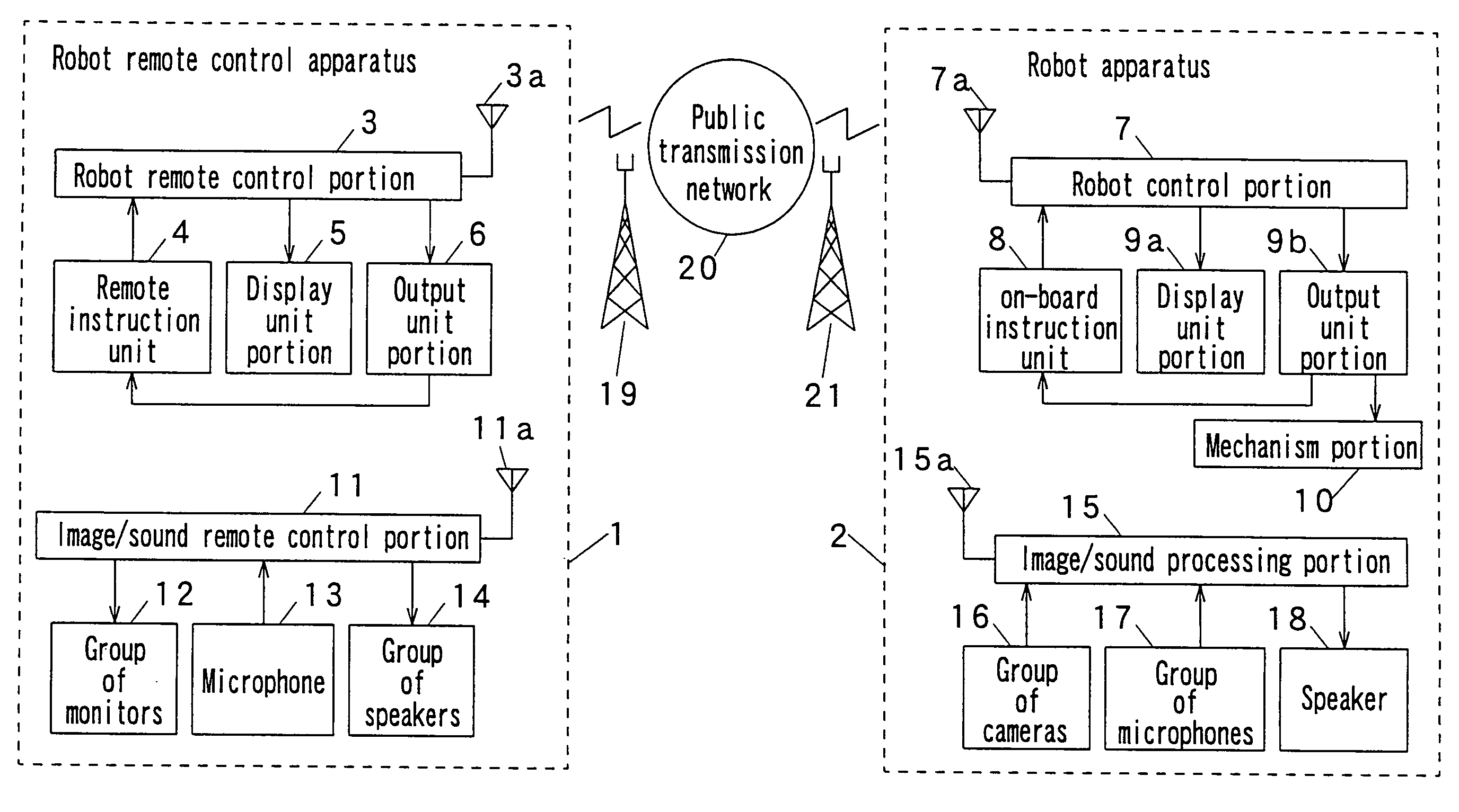
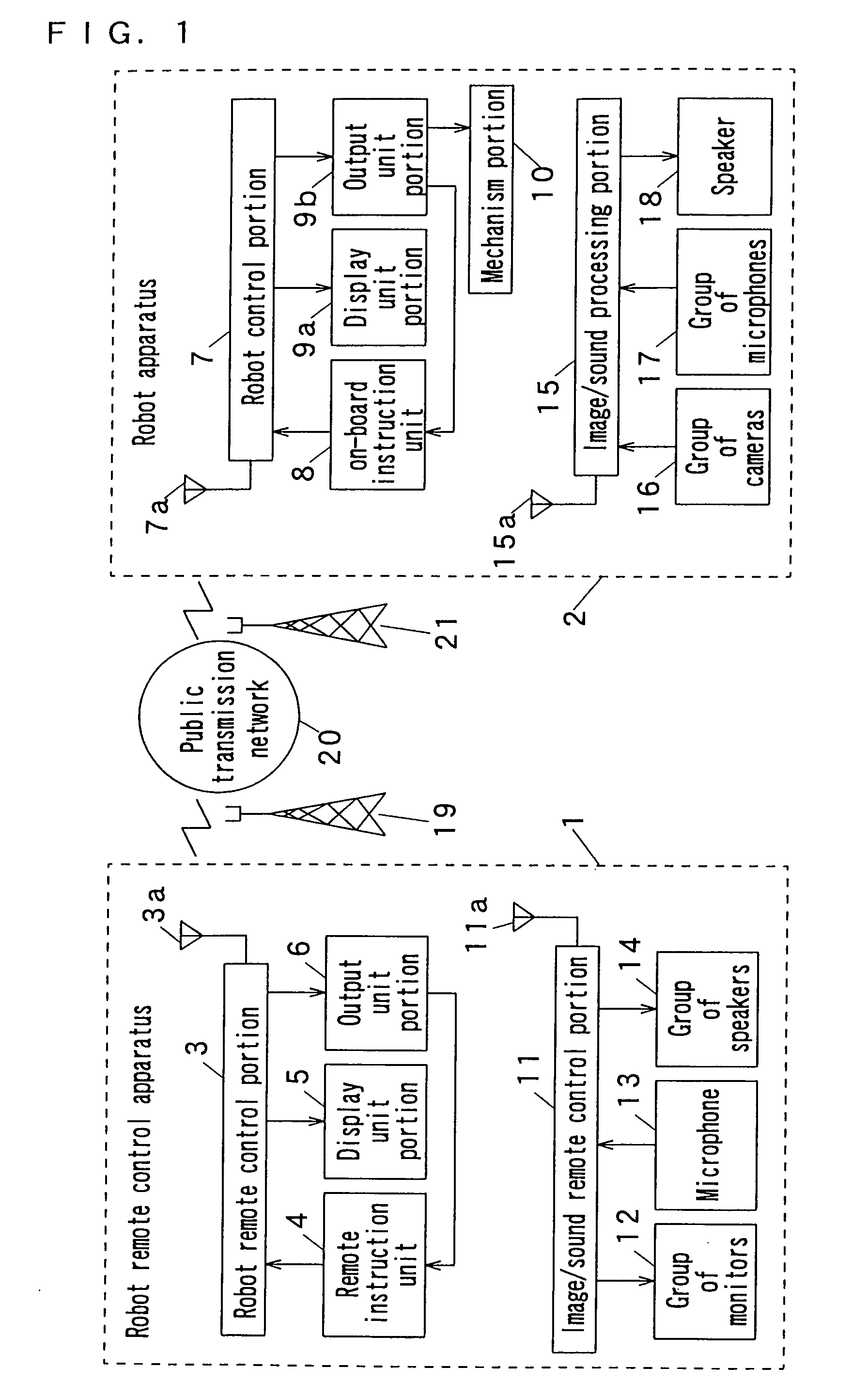
[0063]FIG. 1 is a block diagram depicting a remote control system for robot according to Embodiment 1 of the invention;

[0064] In FIG. 1, reference numeral 1 denotes a remote control apparatus for remotely controlling a robot apparatus 2 described later. Reference numeral 2 denotes a robot apparatus to be controlled by the robot remote control apparatus 1, and at the same time to transmit images to the robot remote control apparatus 1. Reference numeral 3 denotes a robot remote control portion, and 3a denotes an antenna for transmission and receiving. Reference numeral 4 denotes a remote instruction unit that generates remote instruction signals (control data). Reference numeral 5 denotes a display unit portion that has various types of display units (herein, only the display unit is illustrated as an example). Reference numeral 6 denotes an output unit portion that has various types of output units. Reference numeral 7 denotes a robot control portion that controls the entirety of t...


PUM


Abstract

An object of the invention is to provide a remote control system for robot in which a remotely controlled robot apparatus is capable of carrying out skillful movement and movement for removing a heavy load. A robot remote control apparatus 1 includes a remote instruction unit 4 for generating control data for the robot apparatus 2, a first computer unit for inputting and processing the control data, and a first mobile transmission unit for transmitting the control data to a base station 19 connected to a public transmission network 20; the robot apparatus 2 includes a second mobile transmission unit for receiving the control data transmitted from the base station 21 connected to the public transmission network 20 and a second computer unit for processing the control data and controlling a mechanism portion 10; the mechanism portion includes one or two heavy-load working arms, one or two light-load working arms, and a traveling system, all of which are controlled by the second computer unit; and the second computer unit controls the one or two heavy-load working arms, the one or two light-load working arms and the traveling system on the basis of the control data for the robot apparatus 2.

Description

TECHNICAL FIELD OF THE INVENTION [0001] The present invention relates to a remote control system for robot, which remotely controls the robot apparatus based on control data radio-transmitted from a robot remote control apparatus for the purpose of rescuing an object to be rescued such as a human being and restoration work at a dangerous site. BACKGROUND ART OF THE INVENTION [0002] For example, a system disclosed in Japanese Published Unexamined Utility Model Application No. Hei-6-68977 is available as a remote control system for robot for remotely controlling a rescue robot apparatus. [0003] A robot apparatus in the remote control system for robot described in the above-described published application conveys an object person to be rescued, who is placed on its base frame, in which the object person to be rescued is moved by remote-controlled slave manipulator arms while observing a shot image picked up by a television camera, and is placed on its base frame for rescue. [0004] Howe...

Claims


Application Information

Patent Timeline
IPC IPC(8): G06F19/00B25J13/00B25J3/04B25J5/00B25J9/16B25J13/02
CPCB25J9/1689B25J13/02G05B2219/40174B25J3/04B25J5/005B25J9/0087
Inventor BABA, KATSUYUKIINO, SHIGEAKITAKAMOTO, YOICHI
Owner TIMSUK
Why Eureka
Try Eureka