
Failure communication method

a communication method and failure technology, applied in the field of failure communication in a large-scale computer system, can solve the problems of increasing cost, increasing the cost, and reducing so as to improve the reliability of the system, reduce the amount of incorrect operation and data destruction, and improve the effect of system reliability

Inactive Publication Date: 2006-09-21
FUJITSU LTD
View PDF12 Cites 6 Cited by
  • Summary
  • Abstract
  • Description
  • Claims
  • Application Information

AI Technical Summary

Benefits of technology

[0032] The present invention minimizes incorrect operation and data destruction caused by failure, improves reliability of the system and realizes immediate stop processing at a low cost without increasing signal lines ensuring a highly reliable computer system.

Problems solved by technology

However, in large-scale computer systems, the notification method from interconnecting between all units by exclusive signal lines results in increase in cost because necessity for each units to store partition information of all of the other units and consequent increase in connecting signal lines in attempt to improve usability of the system by configuring a plurality of partitions.
Also, with a method for communicating failure by packets, immediate and simultaneous stop of the partitions is not secured if one-on-one failure notice by failure notice packets is carried out from failed units to all the other units in the same partition.
For example, in the case of failure in the packet transmission circuit or severe failure such as failure in power source of a unit, the failed unit cannot transmit failure notice packet, and therefore the other units constituting the partition cannot be stopped immediately.
It takes some time to stop after failure occurrence, and thus erroneous operation and data destruction etc. occur from being affected by the failed unit during the time period.
Also, it is a problem that the severe failure is not considered.

Method used


Image

  • Failure communication method
  • Failure communication method
  • Failure communication method

Examples


embodiment 1

(Embodiment 1)

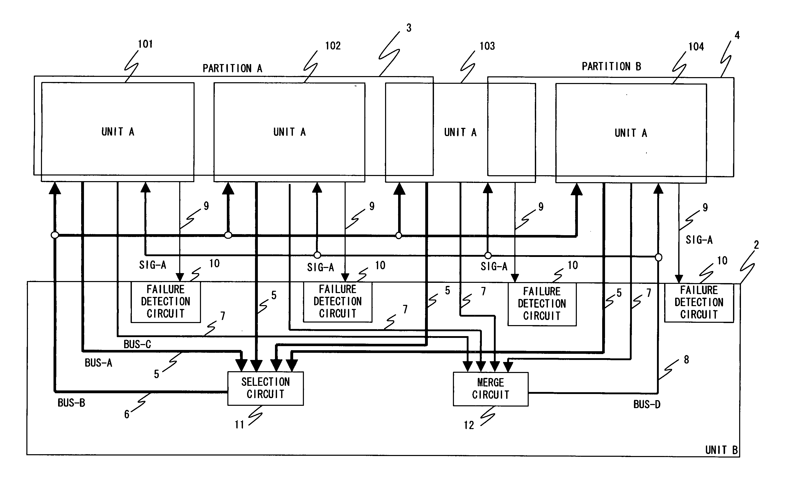
[0043] The system in FIG. 4 comprises a plurality of units A and a unit B2 for controlling each of the units A.

[0044] The units A are separated in a group of a partition A3 or a group of a partition B4; however the unit A103 can be a part of the partition A3 or a part of the partition B4.

[0045] An explanation of the preferred embodiment of the present invention is provided below in conjunction with the accompanying drawings. FIG. 4 is a diagram describing a computer (a large-scale computer system) of the embodiment of the present invention.

[0046] Normally, each unit A separated by each partition, interacts with a unit B2 over BUS-A5 (for example, Local Request Bus), and transmits a request, which is insolvable within the unit A, to the unit B2 (This is (1)′ information transmission shown in FIG. 4).

[0047] And, over BUS-B6 (for example, Global Storage Address Bus), a request received by a section circuit 11 is broadcast to the other units A (This is (2) request tran...

embodiment 2

(Embodiment 2)

[0059] The system in FIG. 4 comprises a plurality of units A and a unit B2 for controlling each of the units A. The units A are separated in a group of a partition A3 or a group of a partition B4; however the unit A103 can be a part of the partition A3 or a part of the partition B4.

[0060] In FIG. 6, a severe failure notification method is explained. When failure is detected in a unit D102 (A), and the failure is so severe that the BUS-C7 cannot be used, the failed unit D102 uses the SIG-A9 and informs the unit B2 that the failed unit D102 is logically separated. Here, SIG-A9 is a signal line (interconnection line) to make the unit B2 recognize the presence of the unit D102.

[0061] Next, the unit B2 recognizes that severe failure occurred in the unit D102 by the SIG-A9. The unit B2 transfers and recognizes severe failure information to the merge circuit 12 instead of a failed unit D102, at the timing that the failed unit D102 has to transmit failure information using t...


PUM


Abstract

A communication method for detecting failure and for performing immediate stop processing is provided. It is a failure communication method of a computer, comprising a plurality of units A, separated by partitions, and a unit B interconnecting the units A, in which the unit B broadcasts identical information, generated based on information transferred from the units A to the unit B, to the units A, wherein when failure occurs in a unit A, the unit B is notified of failure information, receives the failure information, generates identical failure information based on the failure information and notifies the units A in normal conditions of the identical failure information, and the units A receive the identical failure information, if it is from a unit A belonging to the same partition, operation of the units A belonging to the same partition is s topped immediately, and otherwise operation of the units A is continued.

Description

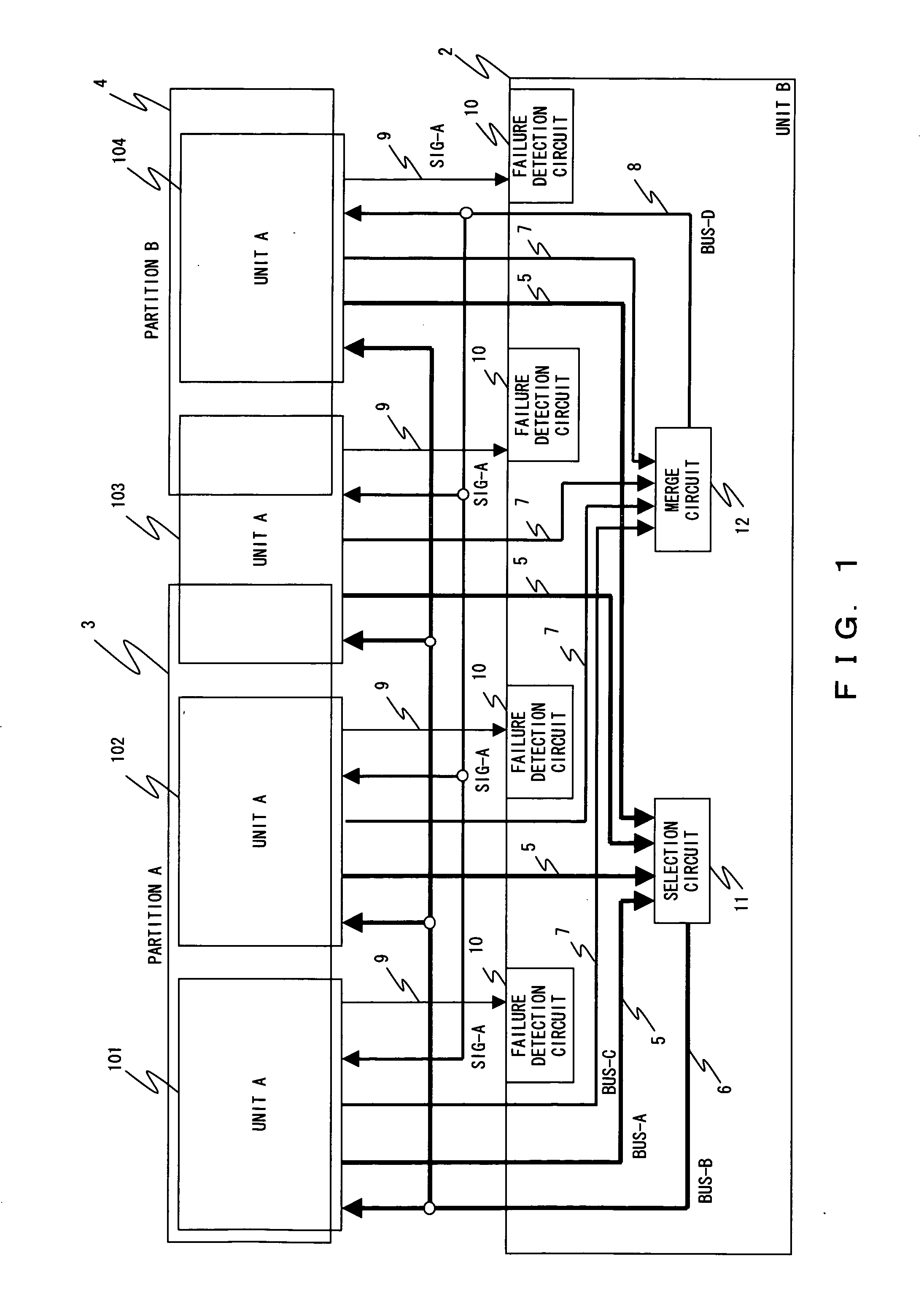
BACKGROUND OF THE INVENTION [0001] 1. Field of the Invention [0002] The present invention relates to failure of communication in a large-scale computer system and specifically to a technology for notifying failure in a partitioned large-scale computer system. [0003] 2. Description of the Prior Art [0004] Recently, large-scale computer systems have comprised of a plurality of units, and a plurality of the units constituting the systems have been configured so as to respond flexibly to the loading state by separating into each computer or partitioned computer (partition: a unit which is a part of the system but can be operated independently). [0005] For example, a system configuration shown in FIG. 1 can be a possible example. [0006] The system in FIG. 1 comprises a plurality of units A101, 102, 103, 104 (101-104 and a unit B2 for controlling each of the units A101-104. Each of the units A are separated by partition in the way as indicated by a partition A3 and a partition B4, for exa...

Claims


Application Information

Patent Timeline
Patent Type & Authority Applications(United States)
IPC IPC(8): G06F11/00
CPCG06F11/0712G06F11/0775G06F11/0784G06F11/30
Inventor KAWAHARA, SHIGERUKINOSHITA, TAKAYUKIITOZAWA, SHINTAROHOSOE, KOJISATO, SAKUTARO
Owner FUJITSU LTD
Learn More