Air pollution control system for ocean-going vessels

a technology for air pollution control and ocean-going vessels, applied in the direction of marine propulsion, vessel construction, separation processes, etc., can solve the problems of pollution that can affect the efficiency and service life of the scr, affect the health of port workers and residents of surrounding communities, and may cause cosmetic and/or physical damage to local structures and equipment, so as to reduce the amount of oxide of nitrogen, reduce the effect of particulate matter and reducing the effect of pollution

Active Publication Date: 2006-09-28
ADVANCED ENVIRONMENTAL GRP +1
View PDF9 Cites 45 Cited by
  • Summary
  • Abstract
  • Description
  • Claims
  • Application Information

AI Technical Summary

Benefits of technology

The present invention provides a mobile platform mounted emissions control unit (ECU) that can reduce particulate matter (PM), sulfur dioxide (SO2), volatile organic compounds (VOCs), and oxides of nitrogen (NOx) from exhaust emissions of mobile or stationary sources. The first system is an ionizing wet scrubber (IWS) and the second system is a selective catalytic reducer (SCR). The IWS processes the exhaust prior to entering the SCR to improve its efficiency and service life. The SCR uses heat from the diesel generator to convert urea to ammonia for use by the SCR and to heat the exhaust flow into the SCR. The ECU is particularly useful for ocean going vessels (OGVs) and other sources of air pollution that are temporarily stationary or nearly stationary.

Problems solved by technology

The patent text describes a system for reducing emissions from ocean going vessels and land based emissions sources such as trucks or locomotives. The technical problem addressed is the need for a system that can capture and reduce airborne emissions from these sources while they are in motion or temporarily stationary. The main exhaust flow from the vessel or land based sources is a complex mixture of gases and fine particulate matter that can cause health risks and damage to equipment and structures. The system described in the patent text uses a bonnet and duct to carry the main exhaust flow from the vessel to emissions processing equipment on a barge alongside the vessel. The system includes a pre-conditioning chamber, oxidation column, reduction column, and caustic (or polishing) column to process the exhaust. The patent text also describes a high thermal efficiency selective catalytic reduction system that uses heat generated in one part of the system to transfer it to other parts that require heat. However, the system may not be efficient when the vessel uses high-sulfur diesel exhaust, which can lead to clogging and corrosion problems for the selective catalytic reduction system.

Method used


Image

  • Air pollution control system for ocean-going vessels
  • Air pollution control system for ocean-going vessels
  • Air pollution control system for ocean-going vessels

Examples


Embodiment Construction

[0022] The following description is of the best mode presently contemplated for carrying out the invention. This description is not to be taken in a limiting sense, but is made merely for the purpose of describing one or more preferred embodiments of the invention. The scope of the invention should be determined with reference to the claims.

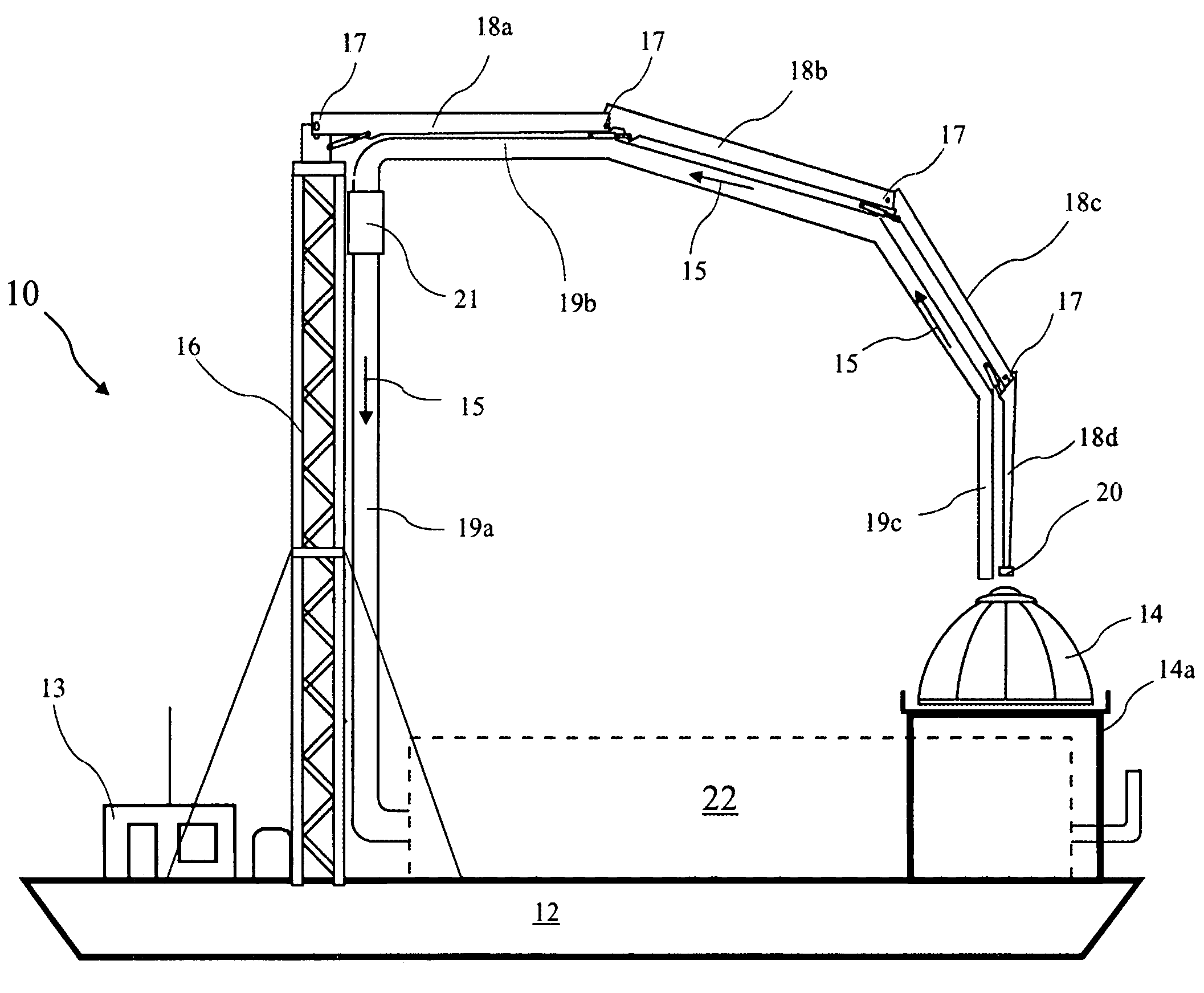
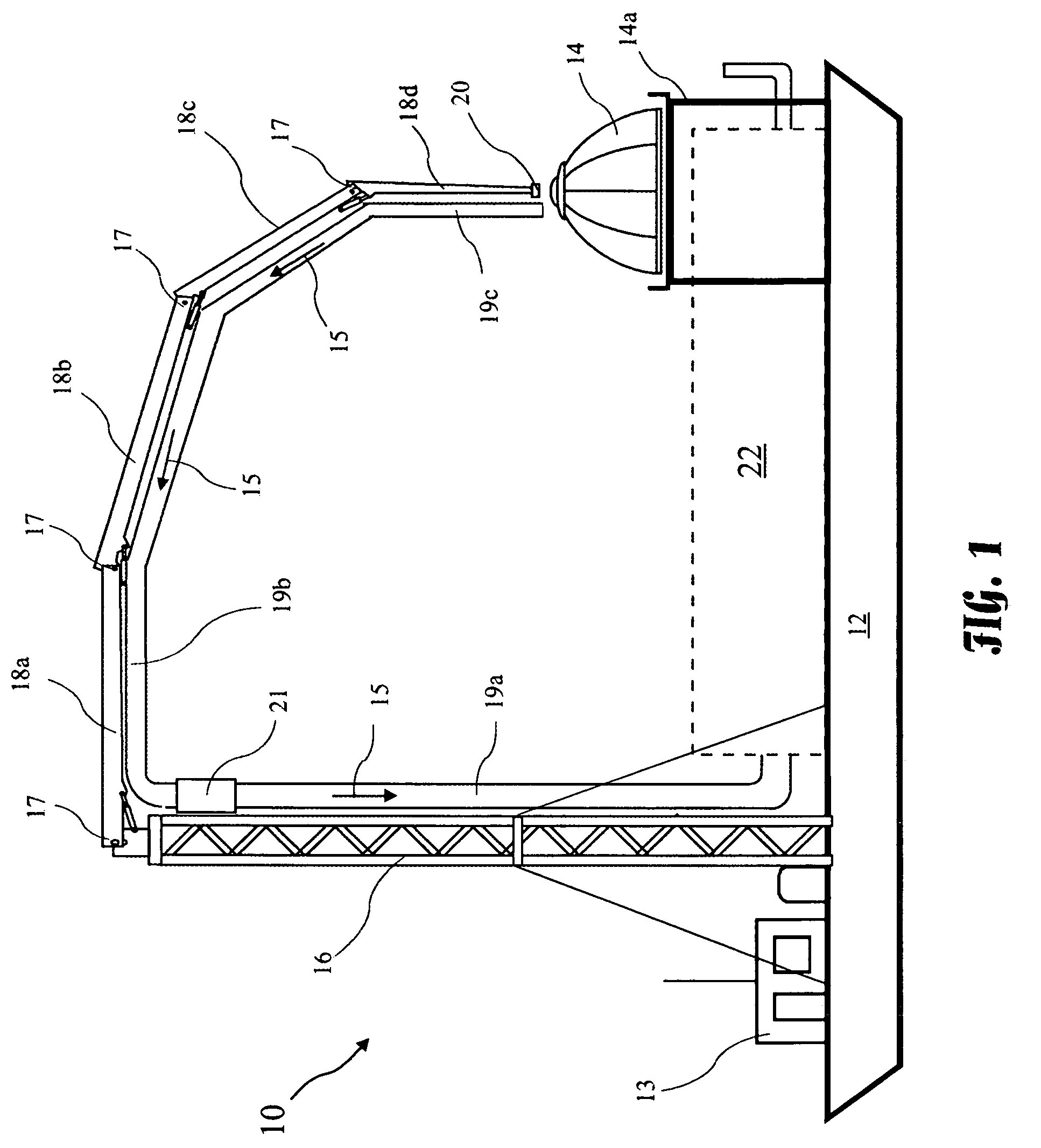
[0023] An Advanced Maritime Emissions Control System (AMECS) 10 suitable for incorporation of the present invention is shown generally in FIG. 1. The AMECS 10 comprises at least one Exhaust Intake Bonnet (EIB) 14, an Emissions Capture System (ECS), and an Emissions Control Unit (ECU) 22. The AMECS 10 is preferably mounted on an Unpowered Seagoing Barge (USB) 12. The ECS comprises a tower 16, an articulating arm comprising four segments 18a, 18b, 18c, and 18d, a duct tower portion 19a running along the tower 16, and duct articulating arm portion 19b running along the actuating arm. The four segments 18a, 18b, 18c, and 18d are connected by joints ...


PUM


Abstract

A platform mounted emissions control unit includes a first system to reduce Particulate Matter (PM), Sulfur Dioxide (SO2), and Volatile Organic Compounds (VOCs), and a second system to reduce Oxides of Nitrogen (NOx). The systems serially process exhaust from a mobile or stationary pollution source. In one embodiment, first system is an Ionizing Wet Scrubber (IWS) and the second system is a Selective Catalytic Reducer (SCR), wherein the IWS processes the exhaust first to improve efficiency and service life of the SCR. A generator produces power required by the IWS and SCR, and heat from exhaust of the generator may be used convert urea to ammonia for use by the SCR, and to heat the exhaust flow into the SCR. The SCR may further include a heat exchanger to capture heat in the flow out of the SCR and use the captured heat to heat the flow into the SCR.

Description


Claims


Application Information

Patent Timeline
Owner ADVANCED ENVIRONMENTAL GRP
Why Eureka
Try Eureka