
Method of manufacturing microstructured optical fiber

Inactive Publication Date: 2006-09-28
FURUKAWA ELECTRIC CO LTD
View PDF15 Cites 20 Cited by
  • Summary
  • Abstract
  • Description
  • Claims
  • Application Information

AI Technical Summary

Benefits of technology

[0010] It is an object of the present invention to at l

Problems solved by technology

However, in the method using the punching jig, when there are an extremely large number of microstructures, labor for manufacturing the preform is large and a size and a structure of the preform that can be formed are limited, making a wide-ranging design of the optical fiber difficult.
However, the general synthetic silica pipe used in this method has low purity compared with a silica glass formed by the MCVD method, the OVD method, or the vapor axial deposition (VAD) method, and contains a large amount of impurities causing a transmission loss.
Therefore, when the synthetic silica pipe is used, a transmission loss of an optical fiber obtained is also high.

Method used


Image

  • Method of manufacturing microstructured optical fiber
  • Method of manufacturing microstructured optical fiber
  • Method of manufacturing microstructured optical fiber

Examples


Embodiment Construction

[0019] Exemplary embodiments of the present invention are explained in detail below with reference to the accompanying drawings. The present invention is not limited by the embodiments.

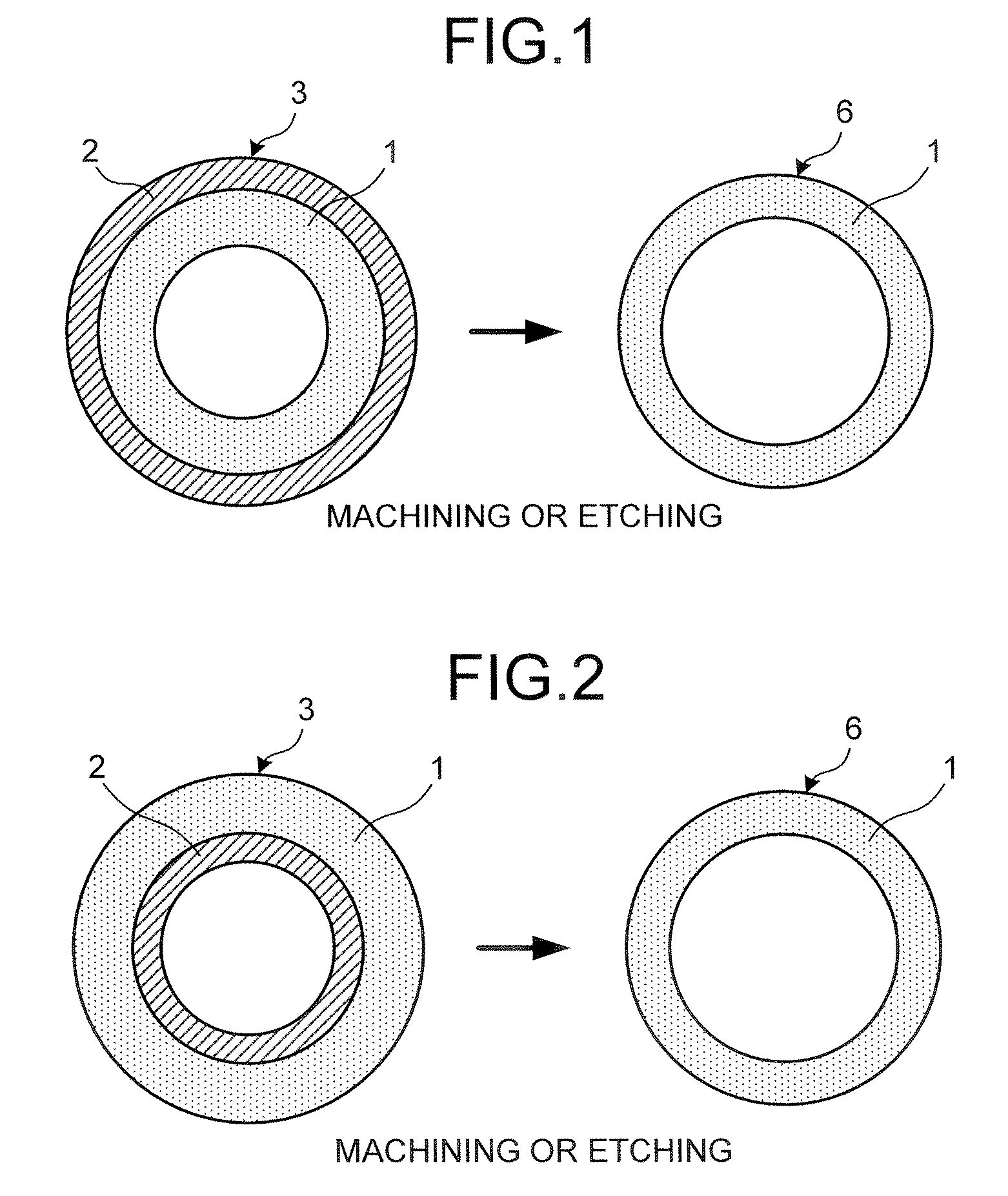
[0020] According to an embodiment of the present invention, a cylindrical intermediate member is manufactured by depositing silica having higher purity than a preform on an inner circumferential surface of a synthetic silica pipe serving as the preform by the MCVD method. Thereafter, a part of the synthetic silica pipe or the entire synthetic silica pipe in the cylindrical intermediate member is removed by etching by a chemical like hydrogen fluoride or machining. In this manner a high-purity silica tube can be obtained. A microstructured optical fiber having a low transmission loss is manufactured using this high-purity silica tube.

[0021] A high-purity silica tube may be obtained using a method of manufacturing a cylindrical intermediate member by depositing silica having high purity on an outer ci...


PUM

PropertyMeasurementUnit
Volumeaaaaaaaaaa
Dimensionless propertyaaaaaaaaaa
Wavelengthaaaaaaaaaa

Abstract

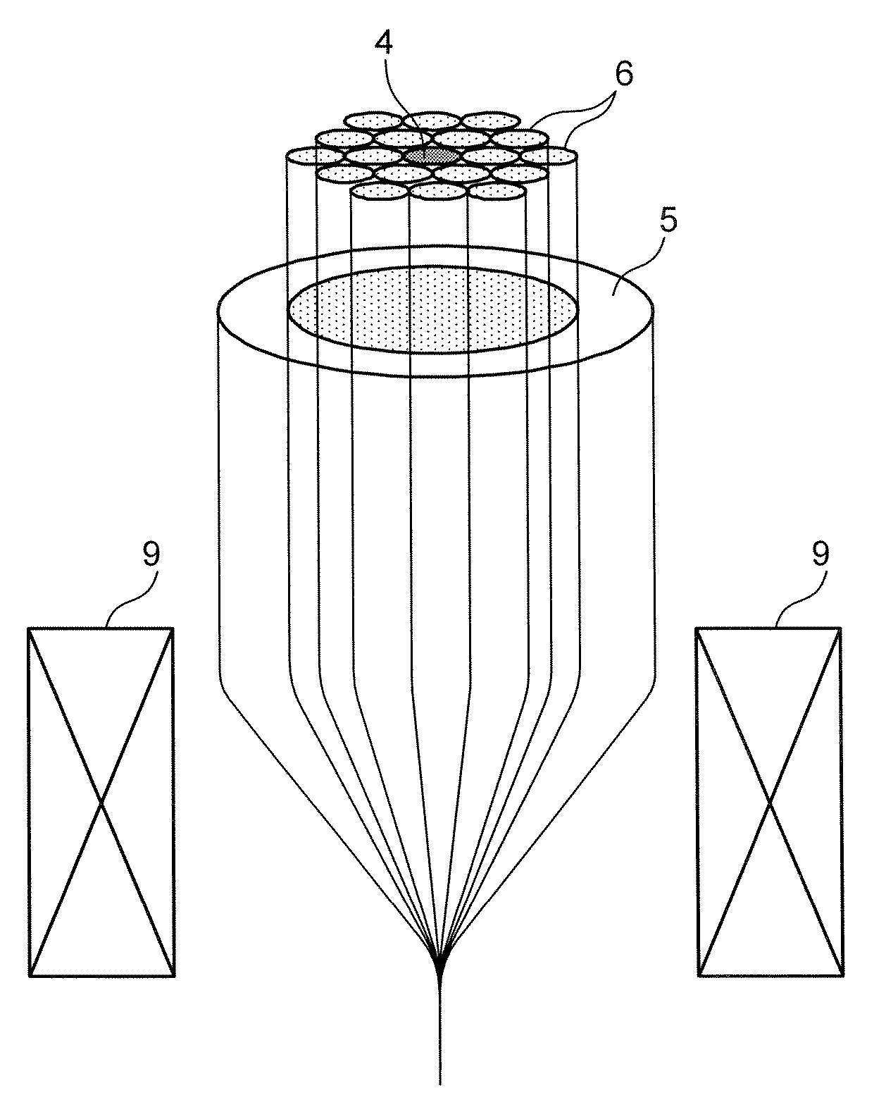
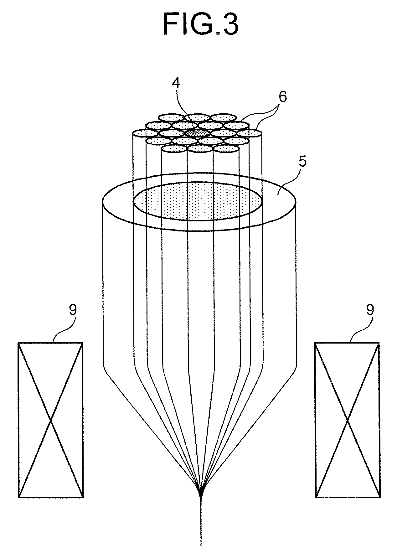
A silica material having a higher purity than a cylindrical preform formed of a silica material is deposited on at least one of an inner side and an outer side of the preform to fabricate a cylindrical intermediate member. A part of the cylindrical intermediate member including at least a part of the preform is removed to fabricate a high-purity silica tube. A plurality of the high-purity silica tubes is bundled with a core rod arranged at a center axis of a bundle of the high-purity silica tubes, and the bundle of the high-purity silica tubes with the core rod arranged at the center axis is drawn to obtain a microstructured optical fiber.

Description

BACKGROUND OF THE INVENTION [0001] 1. Field of the Invention [0002] The present invention relates to a technology for manufacturing a microstructured optical fiber in which a microstructure is formed in a cladding layer. [0003] 2. Description of the Related Art [0004] It is possible to obtain a characteristic that cannot be obtained in the conventional optical fiber by inserting a gas such as the air having an extremely small refractive index compared with a silica glass or a liquid or a solid having a small refractive index into a coaxial layered optical fiber structure. Such a microstructured optical fiber is currently focused on and actively developed. [0005] Forming a microstructure in an optical fiber, various optical fibers can be obtained. Examples of the optical fibers include an optical fiber that can perform a single mode operation in all wavelength bands including visible light and infrared light regions by adjusting a periodic structure of a cladding layer to shift a cut...

Claims


Application Information

Patent Timeline
IPC IPC(8): C03B37/028G02B6/255
CPCC03B37/0122C03B37/01228C03B37/01466C03B37/01861C03B2201/12C03B2201/31C03B2203/42C03C13/00G02B6/02347
Inventor MIYABE, RYOSUGIZAKI, RYUICHI
Owner FURUKAWA ELECTRIC CO LTD
Learn More