Probe for a scanning probe microscope and method of manufacture

a scanning probe and microscope technology, applied in the direction of instruments, mechanical roughness/irregularity measurements, measurement devices, etc., can solve the problems of inability to accurately control the dicing from the backside of the batch fabricated probe assembly, and the difficulty of bulk manufacturing of probes with such short lengths,

Inactive Publication Date: 2006-09-28
VEECO INSTR
View PDF5 Cites 10 Cited by
  • Summary
  • Abstract
  • Description
  • Claims
  • Application Information

AI Technical Summary

Benefits of technology

[0012] The preferred embodiment overcomes the drawbacks of prior art systems by providing a probe that is manufactured so that its length is independent of inherent alignment error(s) associated with the process. In one embodiment, the probe includes a buffer section intermediate the substrate and the cantilever, thus eliminating the drawbacks associated with the uncontrollable offset (caused by alignment error during dicing) present in known techniques of batch fabricating pro

Problems solved by technology

One significant drawback associated with using probes having short cantilevers, however, is that for a number of reasons it is very difficult to bulk manufacture probes having cantilevers with such short lengths, i.e., in the sub-50 micron range.
In the latter regard, when producing short levered probes, it is nearly impossible to accurately control the dicing from the backside of the batch fabricated probe assemblies given alignment inaccuracies in the process.
This offset cannot be readily controlled.
As a result, when batch fabricating such a probe, the uncontrollable offset, “O”, as shown in FIG. 2C, present when the probes are diced operates to limit the manufacturer's ability to produce repeatable probe assemb

Method used


Image

  • Probe for a scanning probe microscope and method of manufacture
  • Probe for a scanning probe microscope and method of manufacture
  • Probe for a scanning probe microscope and method of manufacture

Examples


Embodiment Construction

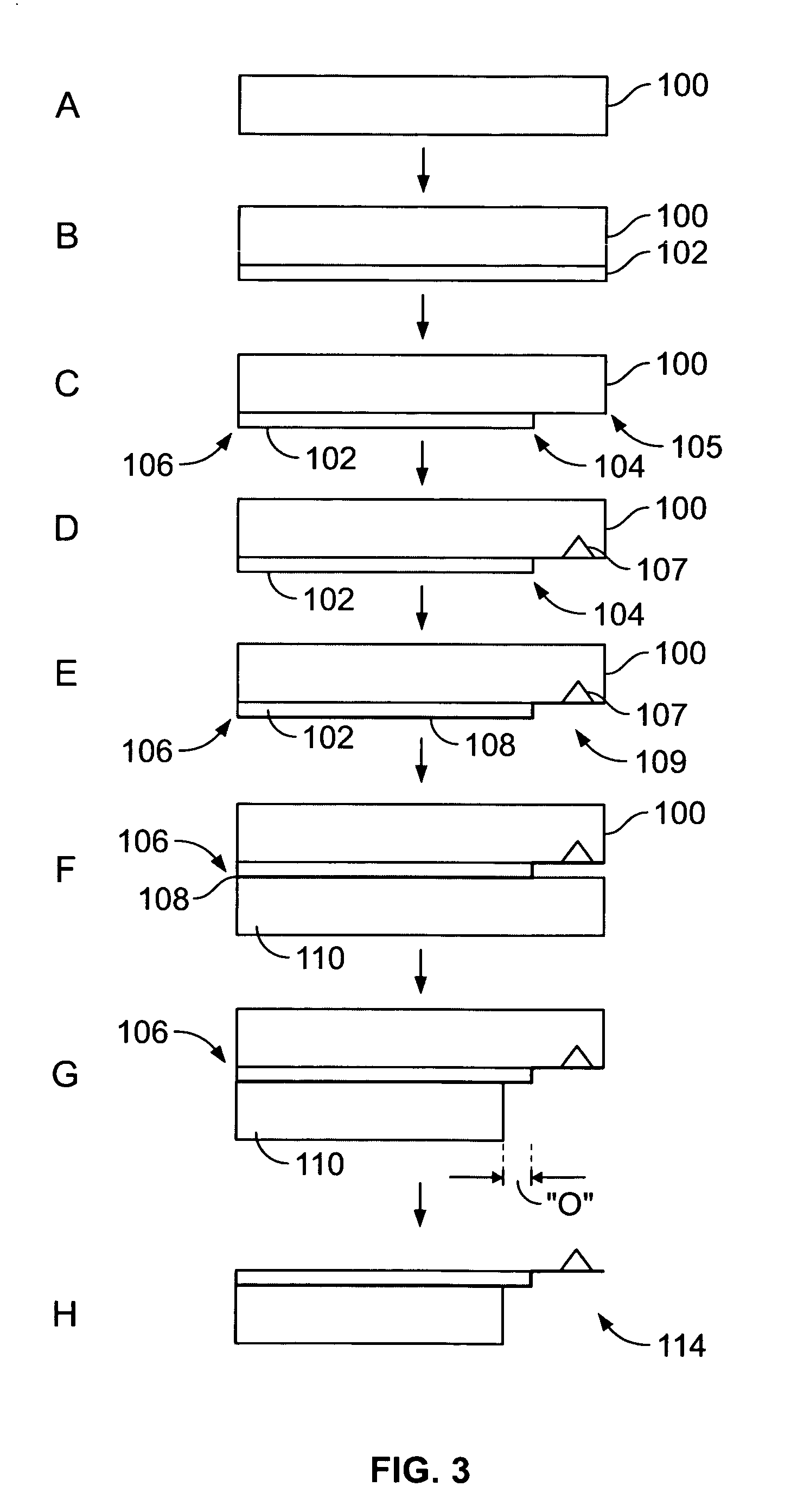
[0040] Turning initially to FIG. 3, the bulk production of a probe assembly having a short, sub-20 micron cantilever, is illustrated in a series of fabrication steps. Moving from top to bottom, the process is initiated with a sacrificial silicon wafer 100 provided in step A. Then, a buffer layer 102 is deposited on the back side of wafer 100 in step B. Buffer layer 102 may be a silicon oxide or a silicon nitride, for instance, and will interface the flexible cantilever of the probe, described further below. Layer 102 is designed to be much stiffer than the cantilever that will ultimately extend therefrom, and facilitates batch fabrication of the probe assembly by eliminating the uncontrollable offset that can result when dicing the probes, and specifically the substrate coupled to the probe during process. This stiffness is preferably achieved by forming layer 102 to have a significantly greater thickness than the layer that will become the cantilever. For instance, the thickness of...


PUM


Abstract

A probe assembly for an instrument and a method of manufacture includes a substrate and a cantilever having a length independent of typical alignment error during fabrication. In one embodiment, the probe assembly includes a buffer section interposed between the substrate and the cantilever. The cantilever extends from the buffer section and a portion of the buffer section extends beyond an edge of the substrate. The portion of the buffer section is more stiff than the cantilever. The corresponding method of producing the probe assembly facilitates batch fabrication without compromising probe performance.

Description

BACKGROUND OF THE INVENTION [0001] 1. Field of the Invention [0002] The present invention is directed to a probe assembly for a metrology instrument used to measure a property of a sample, and more particularly, a probe assembly including a cantilever having a short length to support high bandwidth operation, and configured for ready batch fabrication. [0003] 2. Description of Related Art [0004] Scanning probe microscopes (SPMs), such as the atomic force microscope (AFM), are devices which use a sharp tip and low forces to characterize the surface of a sample down to atomic dimensions. Generally, the tip of the SPM probe is introduced to the sample surface to detect changes in the characteristics of the sample. By providing relative scanning movement between the tip and the sample, surface characteristic data can be acquired over a particular region of the sample and a corresponding map of the sample can be generated. [0005] In an AFM, for example, in a mode of operation called cont...

Claims


Application Information

Patent Timeline
IPC IPC(8): G01B5/28G01D21/00
CPCG01Q60/38B82Y35/00
Inventor KJOLLER, KEVIN J.CHAND, AMIOKULAN, NIHAT
Owner VEECO INSTR
Why Eureka
Try Eureka