
Heat exchanger support structure and heat exchanger supporting method

a technology of heat exchanger and support structure, which is applied in the direction of machines/engines, transportation and packaging, light and heating apparatus, etc., can solve the problems of its manufacturing process and increase the cost of its assembly, and achieve the effect of reducing the manufacturing process and manufacturing cos

Inactive Publication Date: 2006-09-28
CALSONIC KANSEI CORP
View PDF13 Cites 33 Cited by
  • Summary
  • Abstract
  • Description
  • Claims
  • Application Information

AI Technical Summary

Benefits of technology

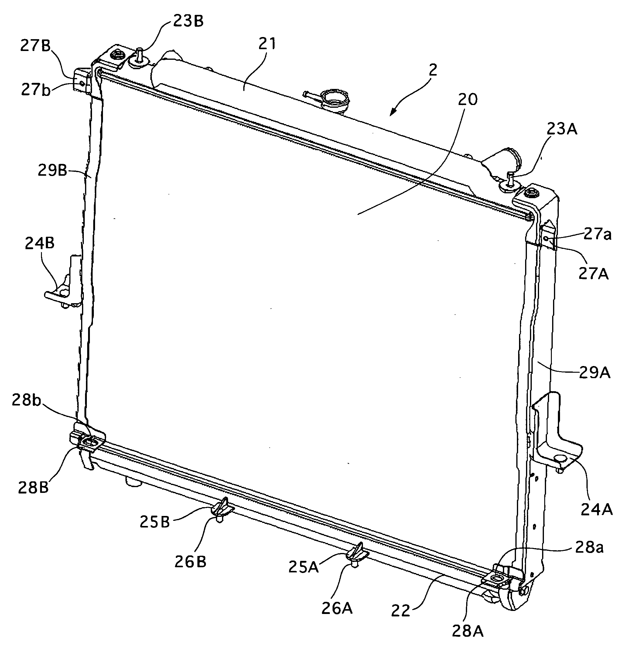
[0008] According to a first aspect of the present invention there is provided a heat exchanger support structure comprising heat exchanger support structure comprising: a first heat exchanger; a second heat exchanger; and a radiator core support for supporting the first heat exchanger. The first heat exchanger has a lower supporting pin projecting downward from a lower portion of the first heat exchanger. The second heat exchanger arranged in front of the first heat exchanger and having an upper portion and a lower portion. The upper portion is supported by the radiator core support and the lower portion is supported by the lower supporting pin of the first heat exchanger so that the lower supporting pin restricts a horizontal movement of the second heat exchanger and allows a vertical movement of the second heat changer.
[0009] This heat exchanger support structure can decrease manufacturing process and manufacturing cost.

Problems solved by technology

However, the conventional radiator core support structure has disadvantages in that its manufacturing process and cost increase in their assembly due to the additional brackets for fixing the second heat exchanger to the radiator core support or due to a complicated-shaped radiator core support.

Method used


Image

  • Heat exchanger support structure and heat exchanger supporting method
  • Heat exchanger support structure and heat exchanger supporting method
  • Heat exchanger support structure and heat exchanger supporting method

Examples


Embodiment Construction

[0037] Throughout the following detailed description, similar reference characters and numbers refer to similar elements in all figures of the drawings, and their descriptions are omitted for eliminating duplication.

[0038] A heat exchanger support structure of an embodiment according to the present invention will be described with reference to the accompanying drawings. In this description, the terms “right”, “left”, “front” and “rear” are those identified with respect to a vehicle body, not to those in the drawings.

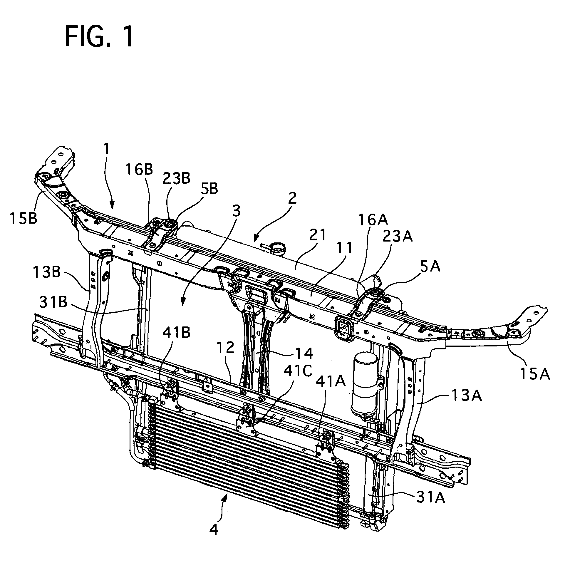
[0039] Referring to FIG. 1, there is shown the heat exchanger support structure of the embodiment, which is attached to a front portion of a not-shown vehicle body of a motor vehicle.

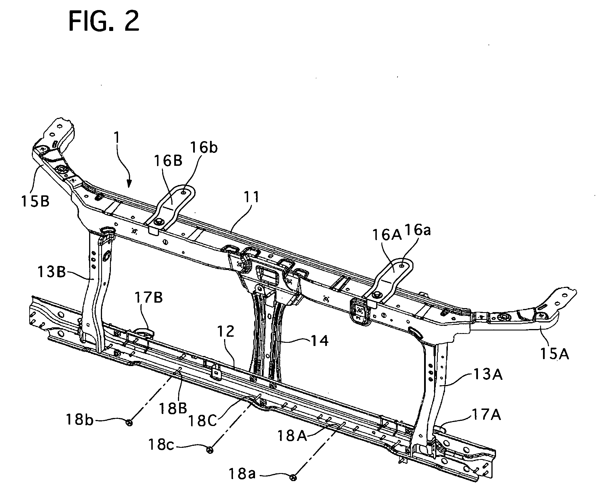
[0040] The heat exchanger support structure includes a radiator core support 1 fixed to the front portion of the vehicle body, a radiator 2 arranged at a rear side of the radiator core support 1, a condenser 3 arranged between the radiator core support 1 and the radiator 2, and an oil coo...


PUM


Abstract

A heat exchanger support structure has a first heat exchanger, a second heat exchanger, and a radiator core support for supporting the first heat exchanger. The first heat exchanger has a lower supporting pin projecting downward from a lower portion of the first heat exchanger. The second heat exchanger arranged in front of the first heat exchanger and having an upper portion and a lower portion The upper portion is supported by the radiator core support and the lower portion is supported by the lower supporting pin of the first heat exchanger so that the lower supporting pin restricts a horizontal movement of the second heat exchanger and allows a vertical movement of the second heat changer.

Description

BACKGROUND OF THE INVENTION [0001] 1. Field of the Invention [0002] The present invention relates to a heat exchanger support structure, which is useful for a motor vehicle, which supports a first heat exchanger and a second heat exchanger, and also relates to a heat exchanger supporting method of the same support structure. [0003] 2. Description of the Related Art [0004] A conventional heat exchanger support structure having a first heat exchanger and a second heat exchanger is disclosed in Japanese Utility Model Laid-open No. Jikkaihei 4-35017. In this conventional support structure, the first and second heat exchangers are supported by a radiator core support secured to a vehicle body. The second heat exchanger is fixed to the radiator core support by additional brackets. [0005] However, the conventional radiator core support structure has disadvantages in that its manufacturing process and cost increase in their assembly due to the additional brackets for fixing the second heat ...

Claims


Application Information

Patent Timeline
Patent Type & Authority Applications(United States)
IPC IPC(8): F28F9/007
CPCB62D25/084F01P2003/187F01P2070/52
Inventor MATSUOKA, IWAOUCHIYAMA, TATSUHIKOHIRAI, TADAHIRO
Owner CALSONIC KANSEI CORP
Learn More