Driving method of liquid drop ejecting head and liquid drop ejecting apparatus

a technology of liquid drop ejection and liquid drop, which is applied in the direction of piezoelectric/electrostrictive/magnetostrictive devices, piezoelectric/electrostriction/magnetostriction machines, etc., can solve the problems of reducing the fluid resistance in the nozzle and liquid supply path, deteriorating the ejector and the refilling ability of the ejector, and achieving excellent ejection of high viscosity liquids

Inactive Publication Date: 2006-09-28
FUJIFILM BUSINESS INNOVATION CORP
View PDF9 Cites 9 Cited by
  • Summary
  • Abstract
  • Description
  • Claims
  • Application Information

AI Technical Summary

Benefits of technology

[0014] The present invention has been accomplished in the light of the above problems, and provides a driving method of a liquid drop ejecting

Problems solved by technology

When high viscosity liquid is to be ejected from an liquid drop ejecting head, however, various problems occur.
For example, when such high viscosity liquid is ejected, ejection efficiency of an ejector and refilling ability of the ejector are deteriorated due to the influence of the viscosity of the ink, it is necessary to increase the size of the pressure chamber, and to design flow paths such that fluid resistance is reduced in the nozzle and liquid supply paths.
Large variation is generated also in the natural oscillation period Tc of pressure wave, and when the environmental temperature is varied to low or high temperature, there is a problem that liquid drop cannot be ejected normally.
According to the technique described in the a

Method used


Image

  • Driving method of liquid drop ejecting head and liquid drop ejecting apparatus
  • Driving method of liquid drop ejecting head and liquid drop ejecting apparatus
  • Driving method of liquid drop ejecting head and liquid drop ejecting apparatus

Examples


Embodiment Construction

[0037] In this embodiment, a case in which the present invention is applied to an ink-jet recording head of a printer will be explained.

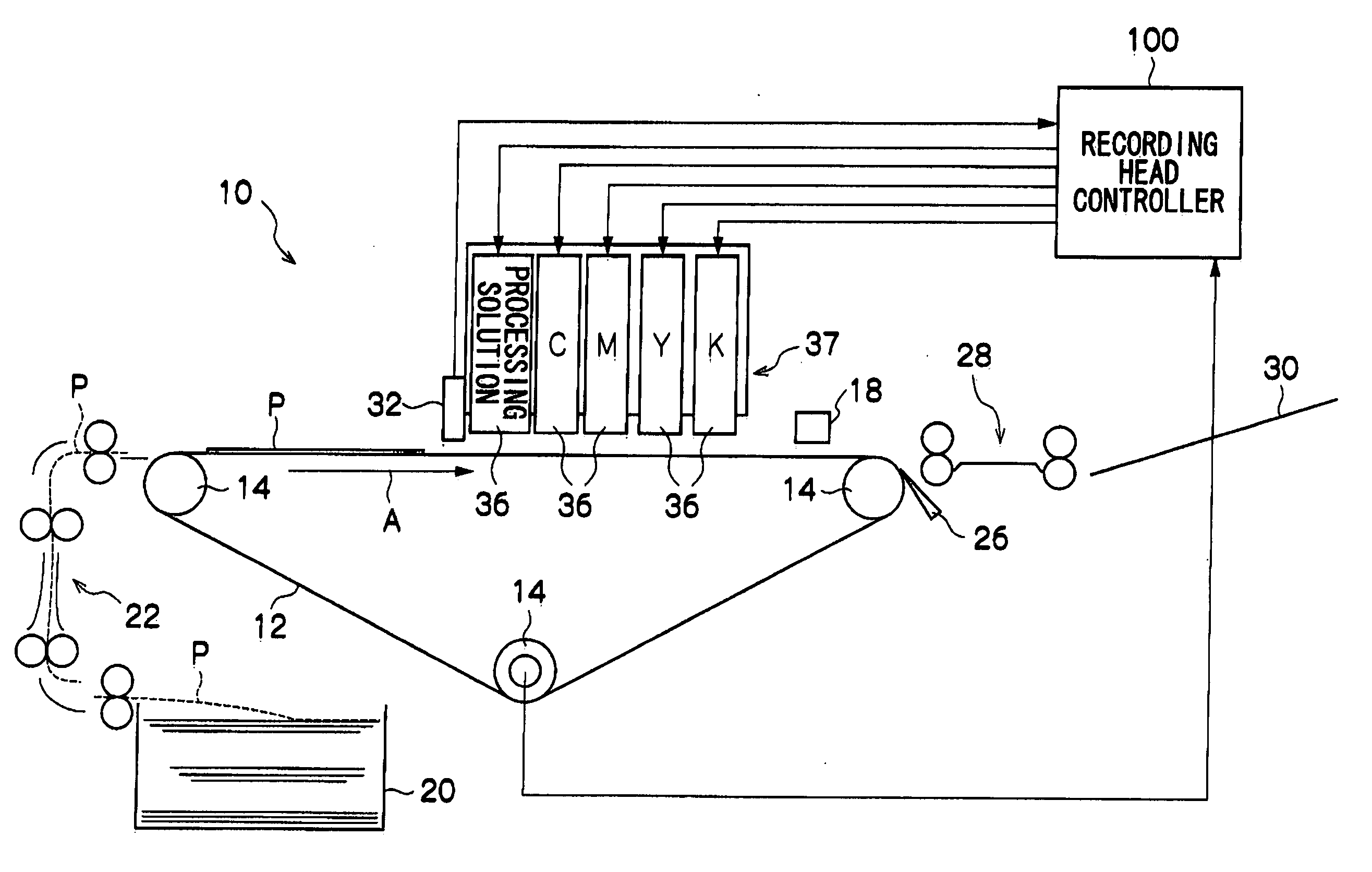
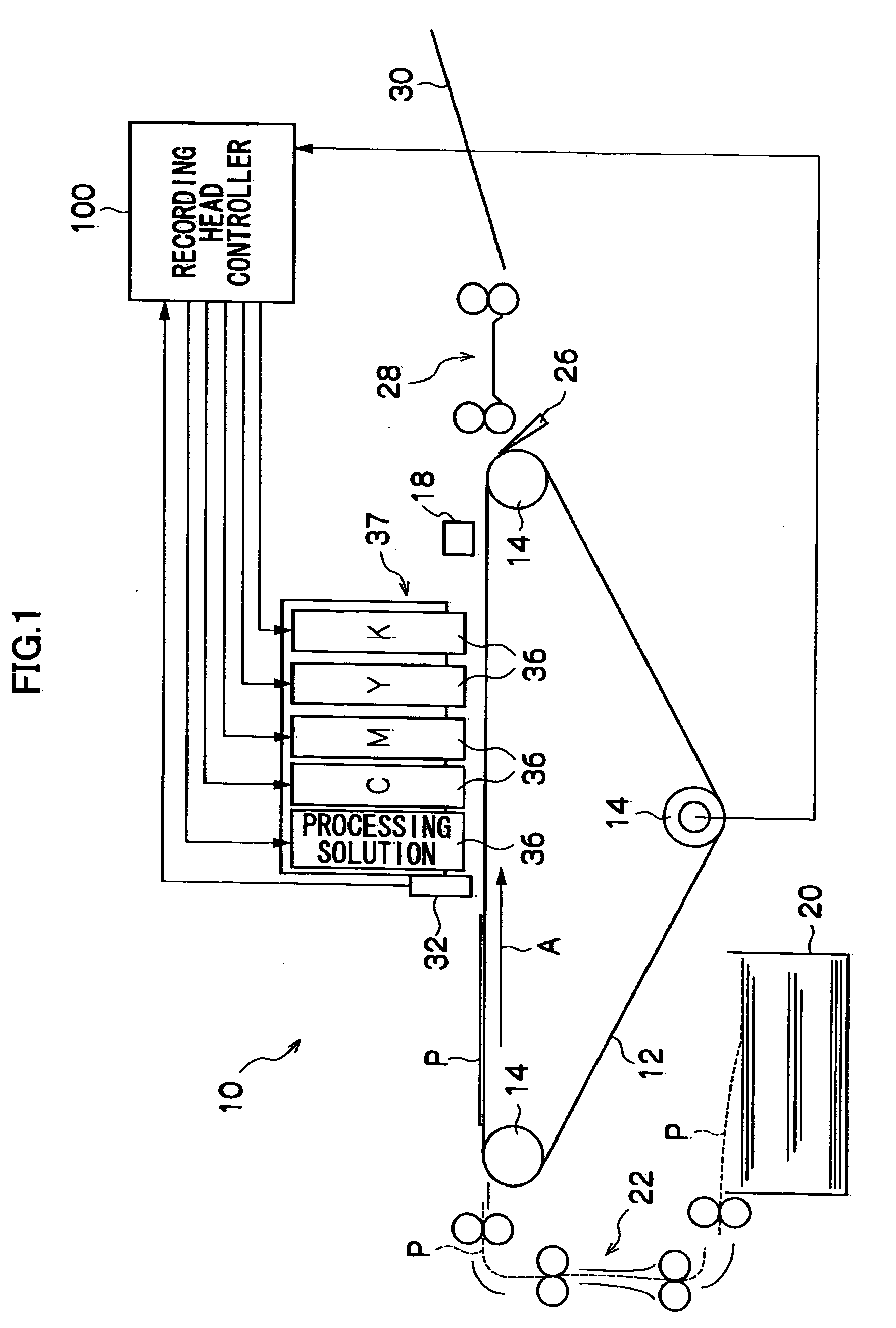
[0038]FIG. 1 is a schematic diagram of a Full Width Array (FWA) type ink-jet printer (simply “printer”, hereinafter) 10 according to the embodiment.

[0039] In the printer 10, a transfer belt 12 is wound around a plurality of rollers 14 and the transfer belt 12 revolves around the rollers 14 in a direction shown with A in FIG. 1. One or more of the rollers 14 are drive rollers, which receive a driving force of a drive (not shown) and rotate, and other rollers 14 follow the drive rollers and rotate.

[0040] A paper tray 20 is disposed in the printer 10, and recording sheets P for recording images are stacked and accommodated in the paper tray 20. The recording sheets P accommodated in the paper tray 20 are taken out one sheet at a time from the uppermost sheet by a pickup mechanism (not shown) and are guided into a sheet transfer path 22, and sent out...


PUM


Abstract

Disclosed herein is a driving method of a liquid drop ejecting head in which an oscillatory wave is imparted to a liquid accommodated in a pressure chamber using an electromechanical transducer, which is driven by applying a predetermined driving waveform to the electromechanical transducer, thereby discharging a liquid drop from a nozzle to record an image. The driving method comprising: detecting an environmental temperature, and expanding and/or contracting the driving waveform to be applied to the electromechanical transducer, in a voltage axial direction and a time axial direction, in accordance with the detected environmental temperature, and applying the resulting driving waveform to the electromechanical transducer. Also disclosed is adjusting the waveform of a reverberation adjustor portion of the driving waveform, which adjusts a residual oscillation of the liquid, in accordance with the detected environmental temperature.

Description

CROSS-REFERENCE TO RELATED APPLICATION [0001] This application claims priority under 35 USC 119 from Japanese Patent Application No. 2005-090082, the disclosure of which is incorporated by reference herein. BACKGROUND OF THE INVENTION [0002] 1. Field of the Invention [0003] The present invention relates to a driving method of a liquid drop ejecting head for discharging liquid drops to record an image. [0004] 2. Description of the Related Art [0005] As liquid drop ejecting heads using an electromechanical transducer (such as piezoelectric actuator), there conventionally exists ink-jet recording heads for discharging ink drops onto recording sheets to record images. [0006] In such an ink-jet recording head of this kind, if a driving waveform is applied to an electromechanical transducer, the meniscus action of a nozzle can be precisely controlled and by doing so, it is possible to undertake high frequency ejection, to eject microdrops, and to prevent satellite drops and mist from bein...

Claims


Application Information

Patent Timeline
IPC IPC(8): H01L41/00B41J2/015B41J2/045B41J2/055B41J2/135B41J2/14
CPCB41J2/04563B41J2/04581B41J2/04588
Inventor OKUDA, MASAKAZU
Owner FUJIFILM BUSINESS INNOVATION CORP
Why Eureka
Try Eureka