
Process for controlling temperature of battery pack

a battery pack and temperature control technology, applied in the field of process for controlling the temperature of a battery pack, can solve the problems of releasing air pollution, deterioration of unit cells, and large amount of heat generated, and achieve optimal operation of the battery system and optimal temperature control

Active Publication Date: 2006-09-28
LG ENERGY SOLUTION LTD
View PDF2 Cites 12 Cited by
  • Summary
  • Abstract
  • Description
  • Claims
  • Application Information

AI Technical Summary

Benefits of technology

[0012] The inventors have performed various experiments and research, and have found that the temperature control by the operation of the fan is effectively accomplished when the difference between the temperature of air supplied by the fan operated on the temperature control system of the battery pack and the temperature of the unit cells is equal to or greater than a predetermined level, and the optimal operation condition of the battery is achieved when the temperature variation of the unit cells are simultaneously controlled by the temperature control system. As a result, the inventors have completed the present invention.
[0013] Consequently, it is a first object of the present invention to provide a process for controlling the temperature of a battery pack that is capable of accomplishing the optimal temperature control by the minimum operation of the fan.
[0014] It is a second object of the present invention to provide a process for controlling the temperature of a battery pack that is capable of accomplishing the optimal operation of the battery system by simultaneous control of temperature variation of each of the unit cells.
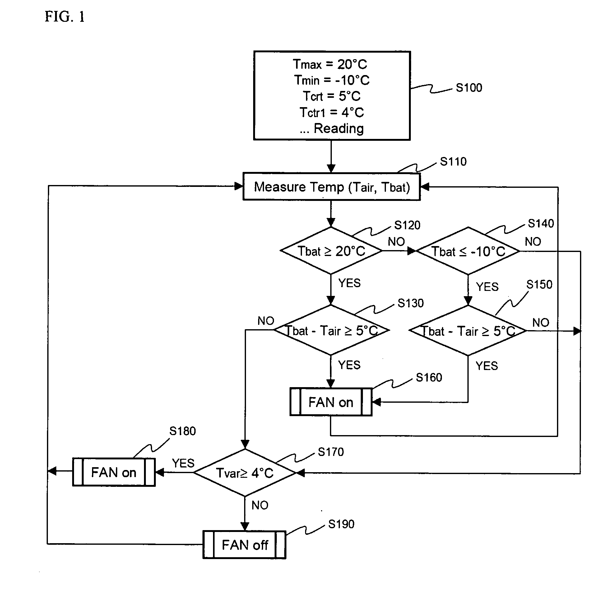
[0016] One of the characteristics of the present invention is that, when the fan of the air conditioning system is operated, and the air, which serves as a heat exchange medium, is supplied to the battery to control the temperature of the battery, it is decided whether the fan is to be operated or not in consideration of the the difference between a battery temperature Tbat and an air temperature Tair (Tbat-Tair) as well as maximum acceptable temperature Tmax and the minimum acceptable temperature Tmin. The temperature control efficiency according to the operation of the fan is not high when the difference between a battery temperature Tbat and an air temperature Tair (Tbat-Tair) is equal to or less than the critical temperature Tcrt although the battery temperature is equal to or greater than the maximum acceptable temperature Tmax, and therefore, cooling is required, or the battery temperature is equal to or less than the minimum acceptable temperature Tmin, and therefore, heating is required. According to the present invention, the fan is operated only when the difference between a battery temperature Tbat and an air temperature Tair (Tbat-Tair) is equal to or greater than the critical temperature Tcrt although the cooling or the heating is required. Consequently, power consumption due to excessive operation of the fan is reduced, and reduction of the service life of the product is prevented.
[0026] As described above, the efficiency of the battery system is remarkably lowered when the temperature variation of the respective unit cells constituting the battery pack is large. Consequently, the operation state of the battery is optimized by the process for controlling temperature of the battery pack according to the present invention.
[0029] According to circumstances, additional steps may be included to increase efficiency of the process for controlling the temperature of the battery pack according to the present invention, and it should be noted that the process for controlling the temperature of the battery pack including the additional steps falls into the scope of the present invention.

Problems solved by technology

One of serious problems concerning vehicles using fossil fuel, such as gasoline or diesel oil, is release of air pollution.
However, the high-output, large-capacity battery has a problem in that a large amount of heat is generated in the course of charge and discharge.
If heat generated from the unit cells in the course of charge and discharge is not efficiently removed, heat is accumulated, and thereby, the unit cells are deteriorated.
However, the conventional process for controlling the temperature of the battery pack has the following problems.
First, only change in temperature of the battery pack is detected to operate the fan while the cooling or heating efficiency of air supplied by the operation of the fan is not considered.
As a result, the efficiency of temperature control according to the operation of the fan is remarkably low.
For example, when the temperature of air introduced by the operation of the fan is high, the cooling effect is low although the driving rate of the fan is high.
Secondly, the deterioration of battery efficiency due to the temperature difference in the unit cells constituting the battery pack is not controlled.
Although one of the principal causes lowering the operation efficiency of the battery system is the great temperature variation between the unit cells, this temperature variation is not considered in the conventional process for controlling the temperature of the battery pack.

Method used


Image

  • Process for controlling temperature of battery pack

Examples


Embodiment Construction

[0032] Now, a preferred embodiment of the present invention will be described in detail with reference to the accompanying drawings. It should be noted, however, that the illustrated embodiment is given merely to assist clear understanding of the present invention, and therefore, the scope of the present invention is not limited by the illustrated embodiment.

[0033]FIG. 1 is a flow chart illustrating a process for controlling the temperature of a battery pack according to a preferred embodiment of the present invention.

[0034] Referring to FIG. 1, when a system for controlling the temperature of the battery pack is operated, values of various parameters are read (S100), and a battery temperature Tbat and an air temperature Tair are measured (S110). The parameters are set as follows: a maximum acceptable temperature Tmax is set to 20° C., a minimum acceptable temperature Tmin to −10° C., a critical temperature Tcrt to 5° C., and another critical temperature Tcrt1 to 4° C. The battery...


PUM


Abstract

A process for controlling temperature of a battery pack includes operating a fan to change a battery temperature to an optimal range of temperature (Topt) when a condition is satisfied that the battery temperature is equal to or greater than a maximum acceptable temperature (Tmax) or when the battery temperature is equal to or less than a minimum acceptable temperature (Tmin) and, at the same time, when the difference between a battery temperature (Tbat) and an air temperature (Tair) of air is equal to or greater than a critical temperature (Tct), and operating the fan to change the battery temperature to an optimal range of temperature variation (Topt1) of each unit cell when the battery temperature does not satisfy the condition, and a temperature variation (Tvar) of each unit cell is equal to or greater than a predetermined critical temperature (Tcrt1). According to the present invention, the operation of the fan is minimized, and therefore, optimal battery operation is accomplished while unnecessary power consumption is reduced. Furthermore, the temperature deviation between the unit cells is reduced, and therefore, the operation of the overall battery system is optimized.

Description

FIELD OF THE INVENTION [0001] The present invention relates to a process for controlling the temperature of a battery pack, and, more particularly, to a process for controlling the temperature of a battery pack that is capable of controlling the operation of a fan in simultaneous consideration of critical values of the maximum acceptable temperature and the minimum acceptable temperature of the battery pack for operation of the fan and a critical value of the difference between the temperature of the battery pack and the temperature of introduced air, when the fan is operated to control the temperature of the battery pack in the case that the battery pack is excessively heated or cooled, and preferably, is also capable of setting a condition for minimizing the temperature variation between unit cells constituting the battery pack to minimally operate the fan, thereby accomplishing an optimal temperature control effect and an optimal battery operation state. BACKGROUND OF THE INVENTI...

Claims


Application Information

Patent Timeline
Patent Type & Authority Applications(United States)
IPC IPC(8): H02J7/04
CPCH01M10/5004H01M10/5008H01M10/5022H01M10/5024H01M10/5067H01M10/5081H01M10/5095H01M10/613H01M10/617H01M10/633H01M10/635H01M10/6563H01M10/657H01M10/663Y02E60/10H01M10/63
Inventor WOO, HYOSANGAHN, JAESUNGPARK, JONGMINJUNG, DO YANGNAMGOONG, JOHN E.
Owner LG ENERGY SOLUTION LTD
Learn More