Supercharge Your Innovation With Domain-Expert AI Agents!

MOSFET temperature compensation current source

a current source and temperature compensation technology, applied in the direction of electric variable regulation, process and machine control, instruments, etc., can solve the problems of increasing mos current through the mos device, and achieve the effect of constant load curren

Inactive Publication Date: 2006-09-28
RFSTREAM
View PDF99 Cites 6 Cited by
  • Summary
  • Abstract
  • Description
  • Claims
  • Application Information

AI Technical Summary

Benefits of technology

[0006] The biasing current generated by the biasing circuit is constant except under temperature or process variations which may cause the biasing current to increase or decrease (due to the effect of temperature or process variations upon the transconductance of the MOS transistors). An increase or decrease in the biasing current (caused by temperature or process variations) produces an increase or decrease, respectively, in the resistor current that flows through the resistor of the load circuit. Temperature or process variations, however, also have an effect on the resistance value (RMOS) of the MOS device of the load circuit and cause the resistance value RMOS to increase or decrease. The changes in the resistance value RMOS also causes a change in the MOS current that flows through the MOS device, whereby the change in MOS current offsets the change in the resistor current to produce a relatively constant load current.

Problems solved by technology

These temperature or process variations, however, also cause the resistance RMOS of the MOS device of the load circuit to increase, thereby causing the MOS current through the MOS device to decrease.
These temperature or process variations, however, also cause the resistance RMOS of the MOS device of the load circuit to decrease, thereby causing the MOS current through the MOS device to increase.

Method used


Image

  • MOSFET temperature compensation current source
  • MOSFET temperature compensation current source
  • MOSFET temperature compensation current source

Examples


Embodiment Construction

[0017] The disclosure of U.S. Provisional Patent Application No. 60 / 660,728, filed Mar. 11, 2005, entitled “A MOSFET Temperature Compensation Current Source,” is hereby expressly incorporated herein by reference.

[0018] Although the present invention is described below in terms of specific exemplary embodiments, one skilled in the art will realize that various modifications and alterations may be made to the below embodiments without departing from the spirit and scope of the invention.

[0019] In the discussion below, Section I describes a constant current source and a method for generating a constant current. Section II describes characteristics of a non-constant current source and a constant current source. And Section III discusses output currents of current sources as a function of the transconductance parameter.

I. Constant Current Source

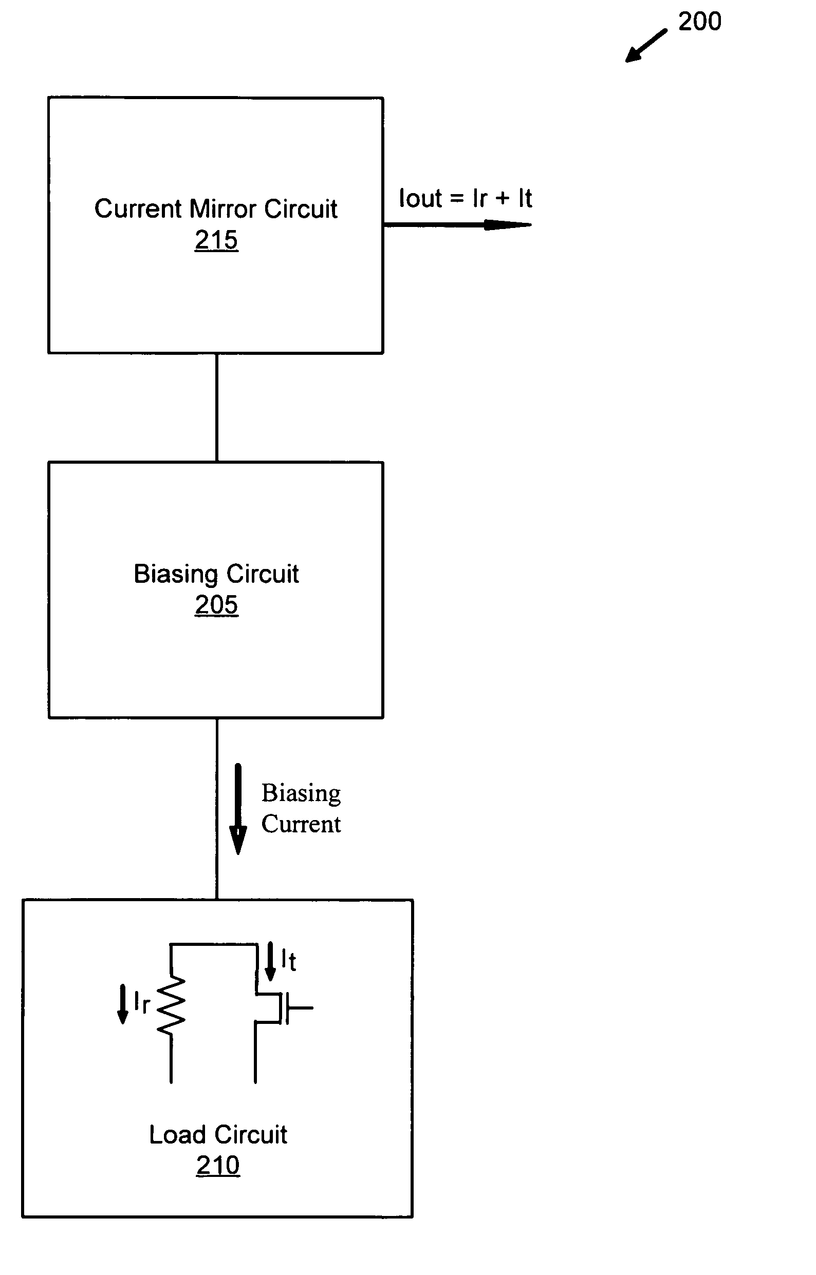
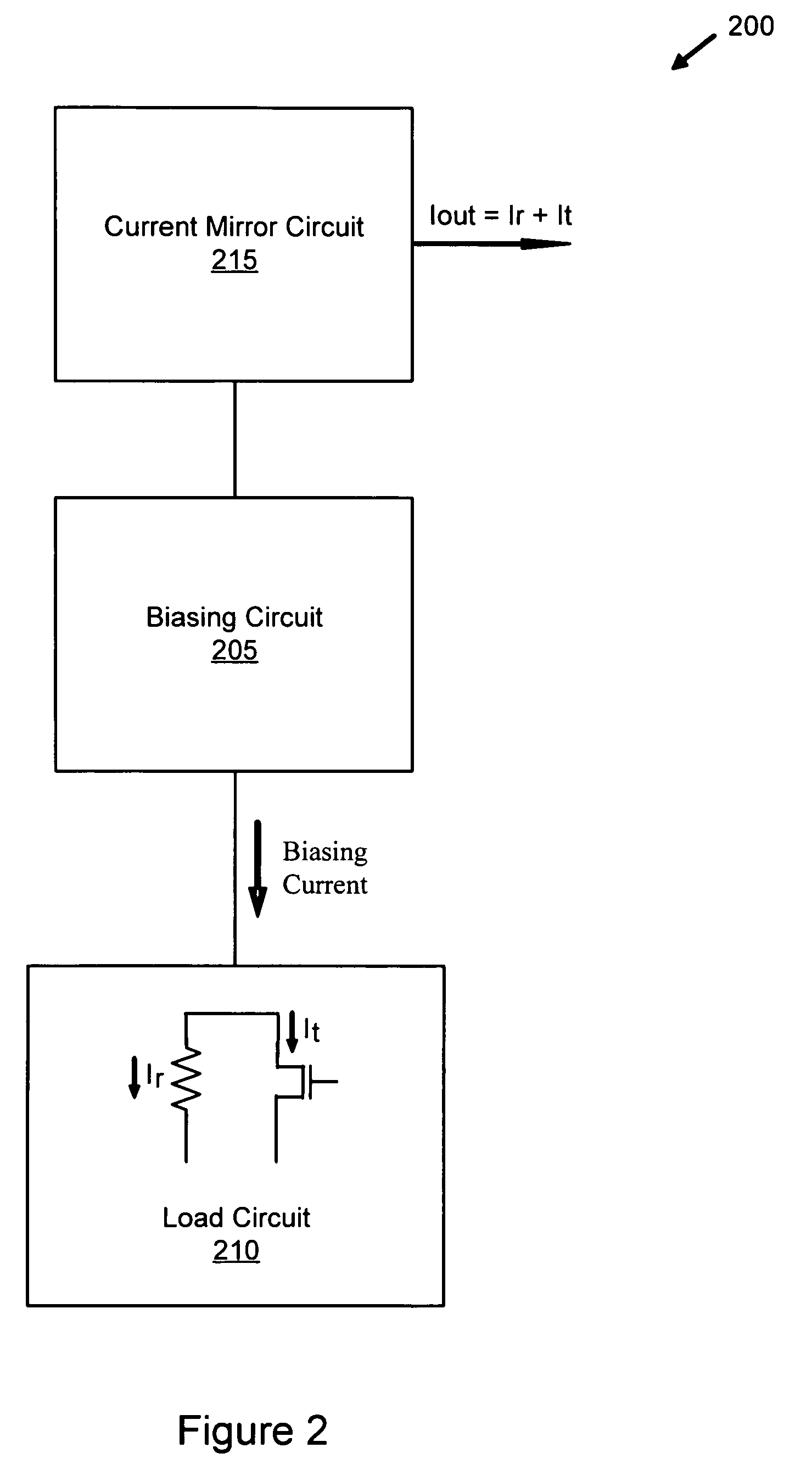
[0020]FIG. 2 is a block diagram illustrating a constant current source 200 of some embodiments. The constant current source 200 comprises a ...


PUM


Abstract

A current source generates a constant current using metal oxide semiconductor (MOS) transistors. A biasing circuit generates a biasing current based on the transconductance of the MOS transistors. A load circuit, comprising a resistor coupled in parallel with a MOS transistor, generates a constant load current from the biasing current. The load current comprises the sum of a resistor current, which flows through the resistor, and a MOS current that flows through the transistor. The load current is constant because variations of the resistor current offset variations of the MOS current across temperature or process variations. A current mirror circuit generates an output current for the current source equal to a sum of the resistor current and the MOS current, the output current being approximately constant in value across temperature or process variations.

Description

CROSS-REFERENCES TO RELATED APPLICATIONS [0001] This application claims the benefit of U.S. Provisional Patent Application No. 60 / 660,728, filed Mar. 11, 2005, entitled “A MOSFET Temperature Compensation Current Source.”FIELD OF THE INVENTION [0002] The present invention is directed towards the field of temperature compensation current sources. BACKGROUND OF THE INVENTION [0003] Current sources are components commonly used in metal oxide semiconductor field effect transistors (MOSFETs). These current sources can be sensitive to temperature or process variations and produce an unstable and variable output current across a range of temperatures and process variations. Typically, current sources are designed to provide a constant current across temperature or process variations using junction diodes. FIG. 1 shows a conventional current source 100 implementing a junction diode 105 to achieve band gap voltage under full complementary metal oxide semiconductor (CMOS) processes. Under CMOS...

Claims


Application Information

Patent Timeline
Patent Type & Authority Applications(United States)
IPC IPC(8): G11C5/14
CPCG05F3/30G11C5/147
Inventor KAMATA, TAKATSUGU
Owner RFSTREAM
Features
  • R&D
  • Intellectual Property
  • Life Sciences
  • Materials
  • Tech Scout
  • Unparalleled Data Quality
  • Higher Quality Content
  • 60% Fewer Hallucinations
Learn More