Inductor

a technology of inductor and substrate, applied in the field of inductor, can solve the problems of poor resistance of inductor to bending, poor standing up, and inability to bend with the substrate, etc., and achieve the effect of accurate and inexpensive changes, easy change of thickness of metal magnetic layer, and easy change of degree of flexibility of inductor as a whol

Inactive Publication Date: 2006-09-28
SUMIDA CORP
View PDF5 Cites 69 Cited by
  • Summary
  • Abstract
  • Description
  • Claims
  • Application Information

AI Technical Summary

Benefits of technology

[0011] With such a structure, because the structural elements of the inductor, that is, the heat-resistant resin film, the insulation layer and the compound magnet are at least flexible, the inductor is flexible. Therefore, the inductor can accommodate bending of the substrate and thus can be mounted on flexible substrates as well. In addition, because the inductor is flexible, it is capable of withstanding the impact of drop tests and the like. Further, providing a compound magnet on the film-type coil increases the inductance of the inductor, enabling it to be used in power lines and the like through which large electric currents flow.
[0026] In addition, according to yet another and further aspect of the present invention, the conductor coil is pattern-formed by etching, electroplating, electrocasting, printing, PVD of or vapor-coating a metal onto the heat-resistant resin film. When so constructed, the thickness of the metal magnetic layer can be easily changed, and as a result, the degree of flexibility of the inductor as a whole also can be changed easily. Moreover, since a uniform layer thickness can be obtained for even complicated shapes, it is possible to increase the accuracy with which the conductor coil is formed.

Problems solved by technology

As a result, the inductor has poor resistance to bending, and moreover, stands up poorly to the impact of drop tests and the like.
In addition, when the inductor is mounted on a flexible substrate, although the conventional rigid inductor can be mounted on the substrate if it is a small one, a large one quickly becomes unable to bend with the substrate, thus rendering installation on a flexible substrate is impossible.
However, the inductor disclosed in Pat. Pub. No. 2000-91135 is composed of a thin copper sheet sandwiched between insulating resin sheets and does not include magnetic material.
As a result, although an air core spiral inductor can be used in a signal line for minute electric currents at high-frequency / low inductance, it is difficult to use such an inductor in large-current signal lines or power lines and the like, with their high-inductance / high superimposed characteristics.

Method used


Image

  • Inductor
  • Inductor
  • Inductor

Examples


first embodiment

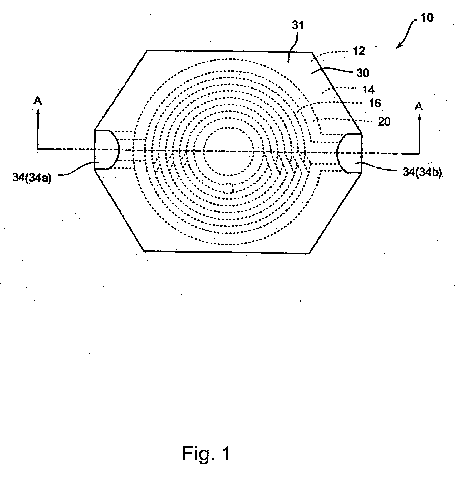
[0047] A description will now be given of an inductor 10 according to a first embodiment of the present invention, using FIGS. 1-10 and TABLE 1.

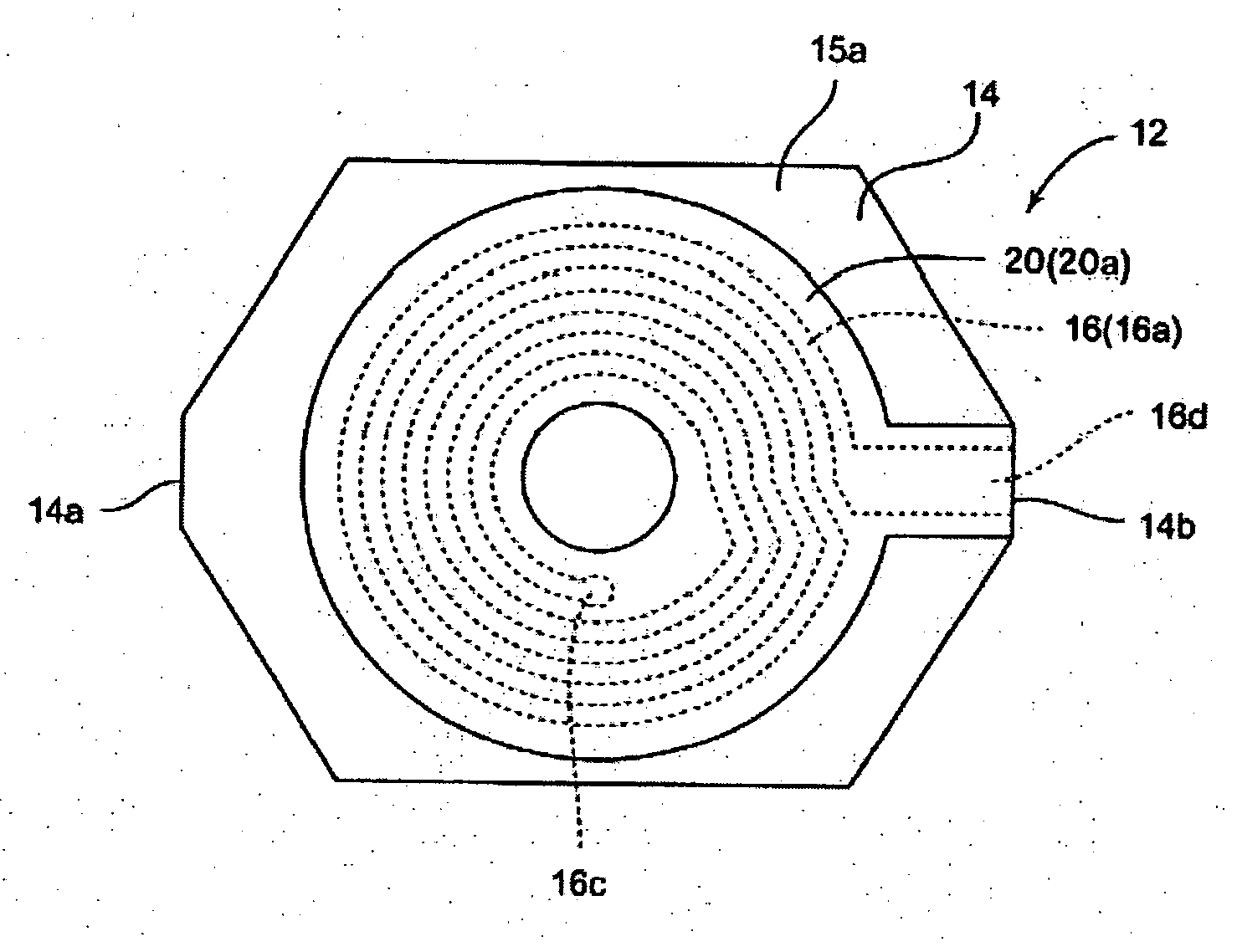
[0048]FIG. 1 is a diagram showing a plan view of an inductor 10 when viewed from the perspective of a surface that is not mounted on a substrate.

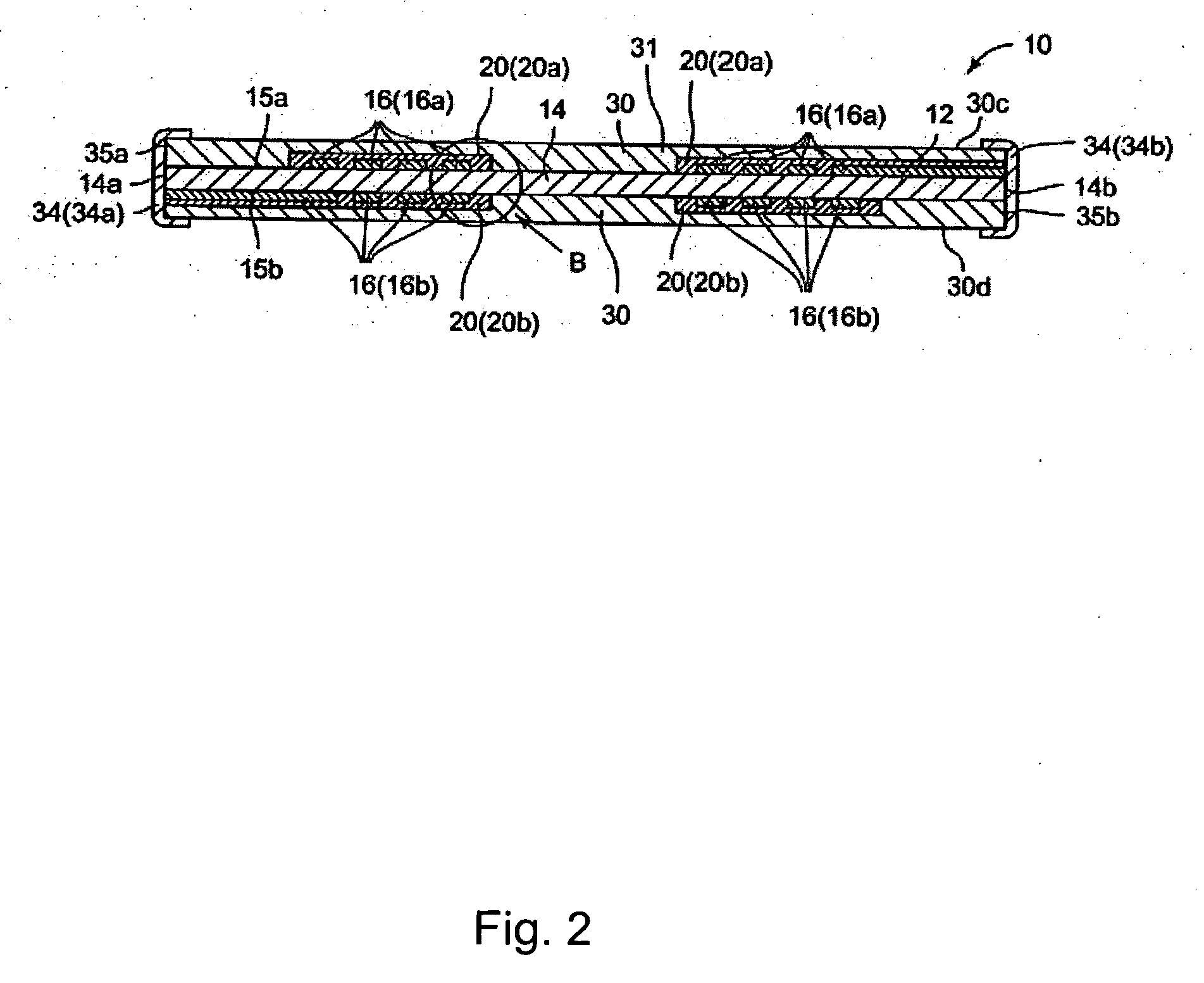
[0049]FIG. 2 is a diagram showing a cross-sectional side view of the structure of the inductor 10 shown in FIG. 1 when cut along a line A-A.

[0050]FIG. 3 is a diagram showing an enlarged view of a part of the inductor 10 shown in FIG. 2 indicated by arrow B.

[0051]FIGS. 4A and 4B are diagrams showing the structure of a film-type coil 12, in which FIG. 4A shows a plan view when seen from above and FIG. 4B shows a plan view when seen from below.

[0052]FIG. 5 is a diagram showing a cross-sectional side view of the film-type coil 12 shown in FIG. 4.

[0053]FIG. 6 is a diagram showing an enlarged view of a part of the film-type coil 12 shown in FIG. 5 indicated by arrow C.

[0054]FIGS. 7A, 7B and 7C are ...

second embodiment

[0079] A description will now be given of an inductor 80 according to a second embodiment of the present invention, with reference to FIGS. 11-17 and TABLE 2.

[0080]FIG. 11 is a diagram showing a plan view of an inductor 80 when viewed from the perspective of a surface that is not mounted on a substrate. FIG. 12 is a diagram showing a cross-sectional side view of the structure of the inductor 80 shown in FIG. 11 when cut along a line D-D. FIG. 13 is a diagram showing the structure of the inductor 80 shown in FIG. 11 when cut along a line D-D, and a cross-sectional side view in a case in which the total thickness of the metal magnetic layer (a kind of magnet) 82 is 20 μm. FIG. 14 is a diagram showing the structure of the inductor 80 shown in FIG. 11 when cut along a line D-D, and a cross-sectional side view in a case in which the total thickness of the metal magnetic layer 82 is 100 μm. FIG. 15 is a diagram showing the structure of the inductor 80 shown in FIG. 11 when cut along a li...


PUM

PropertyMeasurementUnit
total thicknessaaaaaaaaaa

Abstract

An inductor that can be mounted on a flexible substrate and which also can be used in large-current signal lines or power lines. The inductor has a film-type coil formed by providing, in order, a heat-resistant resin film, a flexible conductor coil and insulation layer for covering the conductor coil. A compound magnet that combines magnetic powder and resin is disposed on one or both sides of the film-type coil, with the heat-resistant resin film, the insulation layer and the compound magnetic body being at least flexible.

Description

[0001] This application claims the benefit of Japanese Patent Applications No. 2005-083529 filed on Mar. 23, 2005 and No. 2005-196252 filed on Jul. 5, 2005, the entire contents of which are hereby incorporated by reference herein. BACKGROUND OF THE INVENTION [0002] 1. Field of the Invention [0003] The present invention relates to an inductor, and more particularly, to an inductor used in a variety of electronic devices such as mobile telephones and mobile equipment, as well as in electronic instruments for automobiles. [0004] 2. Description of the Related Art [0005] A conventional inductor uses baked ferrite or press-molded metal powder for the core. In addition, even in the type of inductor that uses a hoop or the like for the electrode, the core is very rigid, and thus the inductor hardly ever deforms. As a result, the inductor has poor resistance to bending, and moreover, stands up poorly to the impact of drop tests and the like. In addition, when the inductor is mounted on a fle...

Claims


Application Information

Patent Timeline
Patent Type & Authority Applications(United States)
IPC IPC(8): H01F5/00
CPCH01F17/0006H01F17/0013H01F41/046H01F2017/006H01F27/32
Inventor KAWARAI, MITSUGU
Owner SUMIDA CORP
Why Eureka
Try Eureka