
Image processing method and apparatus, threshold value matrix creating method, image forming apparatus, sub-matrix creating method and program

Active Publication Date: 2006-09-28
FUJIFILM CORP
View PDF7 Cites 22 Cited by
  • Summary
  • Abstract
  • Description
  • Claims
  • Application Information

AI Technical Summary

Benefits of technology

[0011] The present invention has been contrived in view of the foregoing circumstances, an object thereof to be to provide an image processing method, program and apparatus, a threshold value matrix creating method and program, an image forming apparatus, and a sub-matrix creating method and program, whereby both high-quality image formation and recovery to ejection failures (recording failures) can be achieved using a threshold value matrix of relatively large size, such as a blue noise mask, without causing a significant increase in the storage volume.

Problems solved by technology

For example, when a particular nozzle in a group of nozzles fails to eject or malfunctions, the dots that should have originally been deposited by the nozzle are missing, which results in unintended flaws in the form of lines (streaking) in the recorded image on the recording medium, and this streaking is extremely conspicuous.
In particular, in the case of a device composition which completes printing by means of a single sub-scanning operation (a single pass method), using a line-type recording head in which a plurality of nozzle are arranged, it is difficult to cover the droplet deposition position of a malfunctioning nozzle suffering an ejection failure, by means of another nozzle (in other words, a so-called “shingling” operation), and streaking non-uniformity due to malfunctioning nozzles suffering an ejection failure is highly notable, leading to serious deterioration in image quality.
Therefore, a method has been proposed by which, if any of the nozzles is suffering an ejection failure, deterioration in image quality caused thereby is made to be inconspicuous.
However, the technology which changes the nozzles to a combination which does not include malfunctioning nozzles as disclosed in Japanese Patent Application Publication No. 2004-202795 has a drawback in that, if there are a plurality of malfunctioning nozzles within a dithering matrix, then it becomes necessary to provide dithering matrices in accordance with the number of combinations of the nozzles, and the storage volume of all of the dithering matrix data becomes extremely large.
Furthermore, technology which changes the combination of dots as disclosed in Japanese Patent Application Publication No. 2004-202927 is not compatible with cases where dithering matrices having a size of 2×2 pixels or above are used, since the number of combinations involved is enormous.
If the threshold value matrix size is reduced, then the storage volume is reduced accordingly, but in this case, it is not possible to use a blue noise mask, and hence high image quality can not be obtained.

Method used


Image

  • Image processing method and apparatus, threshold value matrix creating method, image forming apparatus, sub-matrix creating method and program
  • Image processing method and apparatus, threshold value matrix creating method, image forming apparatus, sub-matrix creating method and program
  • Image processing method and apparatus, threshold value matrix creating method, image forming apparatus, sub-matrix creating method and program

Examples


Embodiment Construction

General Description of Image Processing Method in an Embodiment of the Present Invention

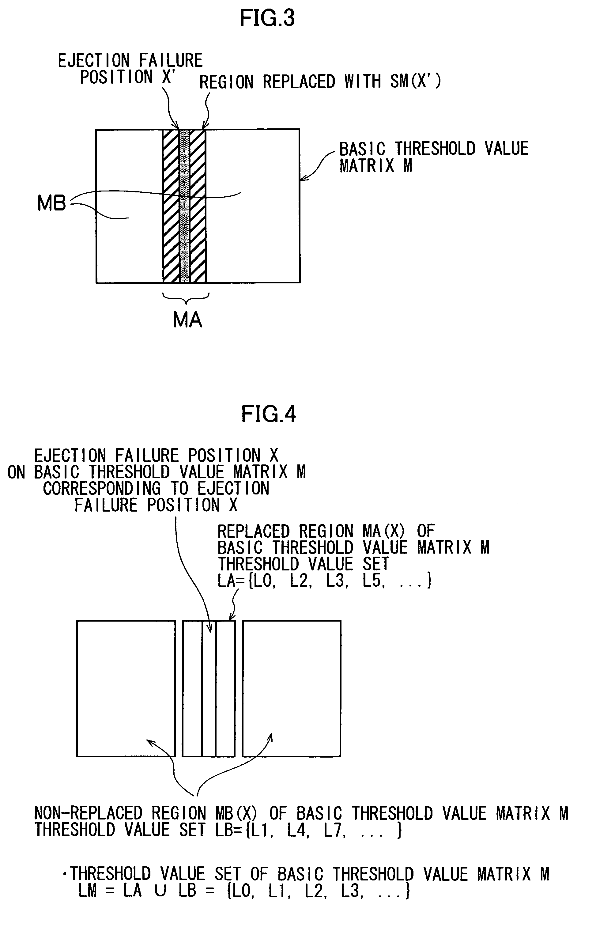
[0070] In the image processing method according to an embodiment of the present invention, threshold values are calculated for regions of a prescribed width corresponding to ejection failure positions beforehand, these threshold values are stored as ejection failure countermeasure sub-matrices, and the ejection failure countermeasure sub-matrix is substituted for a portion of a basic threshold value matrix in accordance with the ejection failure position.

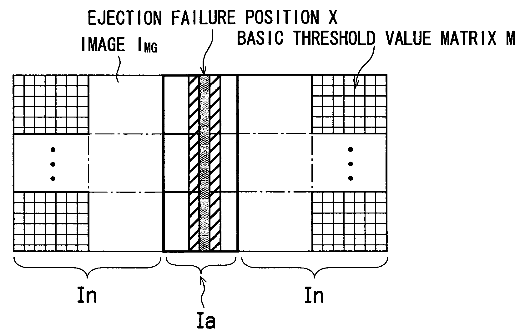
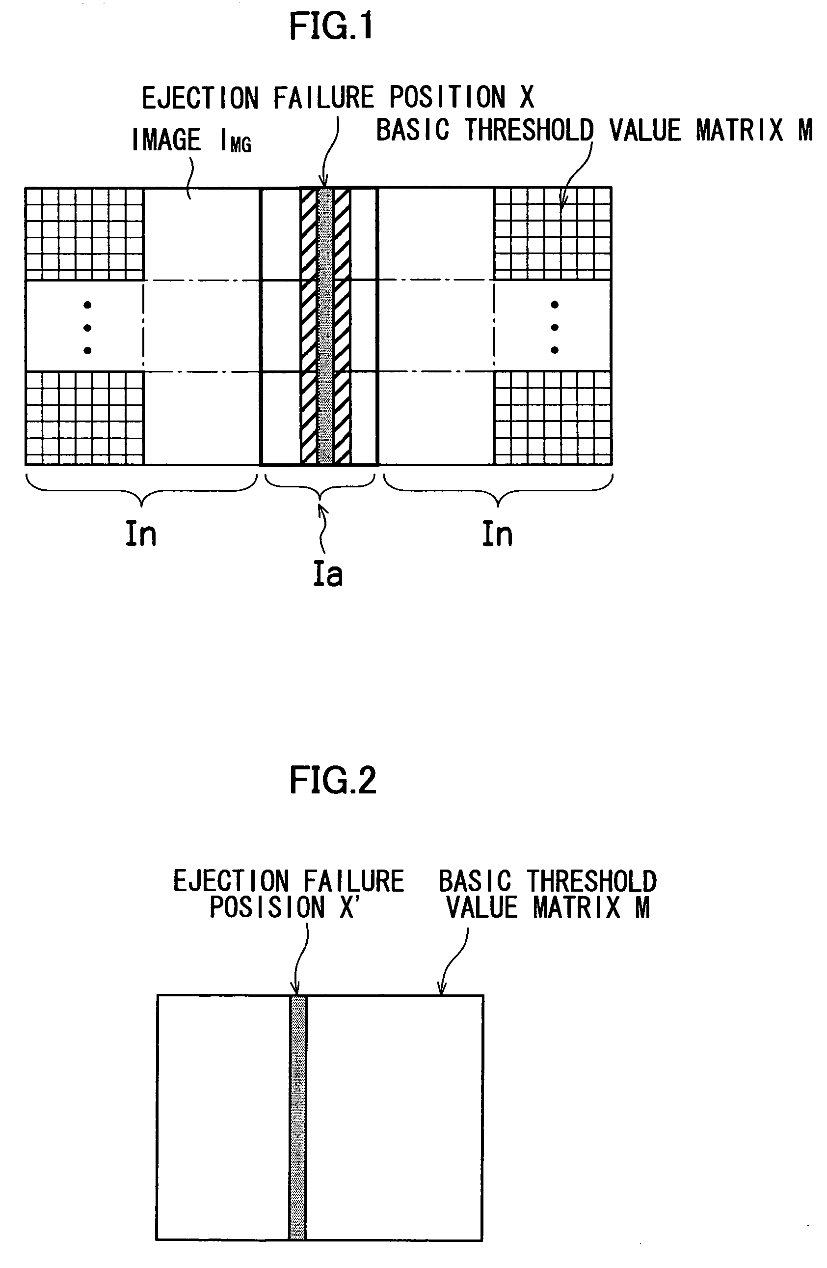
[0071]FIG. 1 is a diagram showing the concept of image processing according to the embodiment of the present invention. As shown in FIG. 1, by repeatedly applying the basic threshold value matrix M with respect to the input image IMG to cover the input image as with tiles, the image is quantized and converted into a pseudo graduated tonal image (dot data). Here, it is supposed that a particular nozzle of the print head (in this case, a line he...


PUM


Abstract

The image processing method comprises: a recording failure position determination step of determining a recording failure position on an image corresponding to a malfunctioning recording element; a basic threshold value matrix storage step of storing a basic threshold value matrix set with threshold values used for halftoning of converting multiple-value input image data into dot data of a number of tonal graduations smaller than that of the multiple-value input image data by quantizing the multiple-value input image data; a sub-matrix storage step of storing a plurality of sub-matrices in association with recording failure positions in the basic threshold value matrix, each of the sub-matrices being set with threshold values which are substituted for the threshold values in a partial region of the basic threshold value matrix, the partial region including a pixel position corresponding to the recording failure position and having a width of a prescribed number of pixels; a replacement region determination step of determining a corresponding region with the width of the prescribed number of pixels including the recording failure position in the basic threshold value matrix, according to the pixel position in the input image data and the recording failure position determined in the recording failure position determination step; a sub-matrix selection step of selecting one of the sub-matrices stored in the sub-matrix storage step to use for substituting for the corresponding region determined in the replacement region determination step; a threshold value replacement step of creating a reformed threshold value matrix by replacing the threshold values of the corresponding region including the recording failure position in the basic threshold value matrix, with the one of the sub-matrices selected in the sub-matrix selection step; and a quantization processing step of quantizing the input image data by selectively using the basic threshold value matrix and the reformed threshold value matrix.

Description

BACKGROUND OF THE INVENTION [0001] 1. Field of the Invention [0002] The present invention relates to an image processing method and apparatus, a threshold value matrix creating method, an image forming apparatus and a sub-matrix creating method and program, and more particularly, to image processing technology suitable for a halftoning process whereby image defects caused by ink ejection failures in an inkjet printer are made to be inconspicuous. [0003] 2. Description of the Related Art [0004] In an inkjet printer, for a variety of reasons, a situation may occur in which it becomes impossible to eject ink from a nozzle. For example, when a particular nozzle in a group of nozzles fails to eject or malfunctions, the dots that should have originally been deposited by the nozzle are missing, which results in unintended flaws in the form of lines (streaking) in the recorded image on the recording medium, and this streaking is extremely conspicuous. [0005] In particular, in the case of a ...

Claims


Application Information

Patent Timeline
IPC IPC(8): B41J2/205
CPCG06K15/02H04N1/4015H04N1/4051
Inventor YAMAZAKI, YOSHIROU
Owner FUJIFILM CORP
Learn More