Ink jet recording head and method of manufacturing the same

a technology of recording head and jet, which is applied in the direction of printing, etc., can solve the problem of unfavorable normal discharge and other problems, and achieve the effect of avoiding the possibility of normal discharg

Inactive Publication Date: 2006-09-28
CANON KK
View PDF4 Cites 0 Cited by
  • Summary
  • Abstract
  • Description
  • Claims
  • Application Information

AI Technical Summary

Benefits of technology

[0009] According to the above-described present invention, any bubble and solid matter such as dust existing in the supplied ink ar...

Problems solved by technology

When the bubble reaches the vicinity of the discharge port, there is the undesirable possibility that normal discharge is not ef...

Method used


Image

  • Ink jet recording head and method of manufacturing the same
  • Ink jet recording head and method of manufacturing the same
  • Ink jet recording head and method of manufacturing the same

Examples


embodiment 1

[0039]FIGS. 5A to 5H are typical perspective views showing a method of manufacturing the ink jet recording head shown in FIG. 4 in the order of steps.

[0040] First, as shown in FIG. 5A, a desired plurality of liquid discharging energy generating elements 2 such as electro-thermal converting members were provided on the semiconductor substrate 3. Then, as shown in FIG. 5B, negative type photosensitive epoxy resin 18 was applied onto the semiconductor substrate 3 by a spin coat method. As the photosensitive epoxy resin 18, use was made of SU-8 (produced by Shell Chemical Co., Ltd.) which is epoxy resist having onium salt as a photosensitive agent, and it was applied with a thickness of 30 μm.

[0041] Thereafter, prebaking for heating this negative type photosensitive epoxy resin 18 at 90° C. for 5 minutes was effected by the use of a hot plate, and exposure of 2 J / cm2 was effected by the use of MPA600 (produced by Canon Inc.) which is a mirror projection aligner. Thereafter, post-expos...

embodiment 2

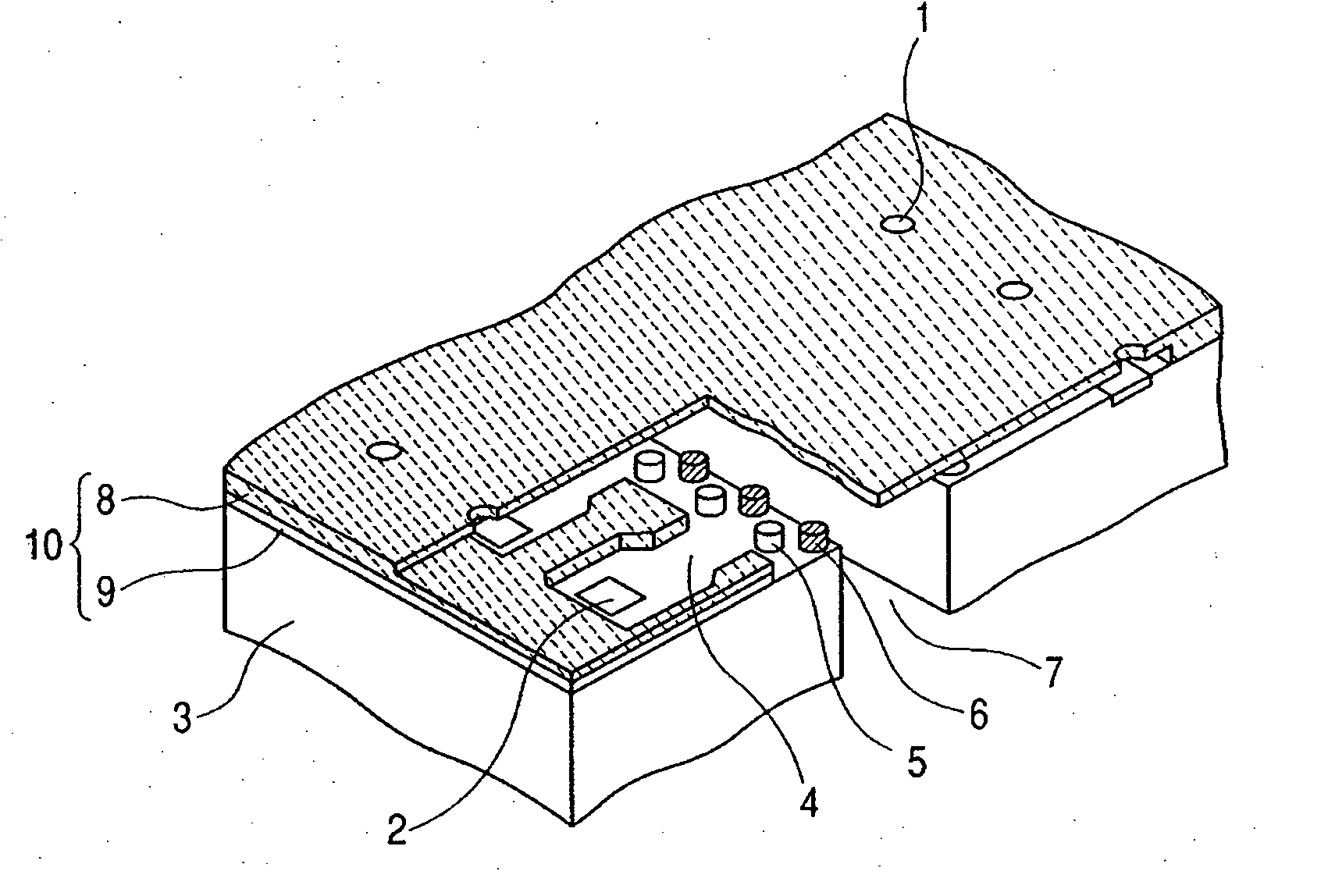
[0047] The protruding portions 6 in Embodiment 1 have the function of catching dust, besides the function of catching any bubble in the ink, but the interval between adjacent ones of the protruding portions 6 is an interval equal to or wider than the diameter of the discharge ports 1 and therefore, the function as a filter for dust may not always be satisfied. So, in order to enhance the filter function to thereby catch more minute dust, protruding portions 5 as a filter for dust catching function may be formed besides the protruding portions 6.

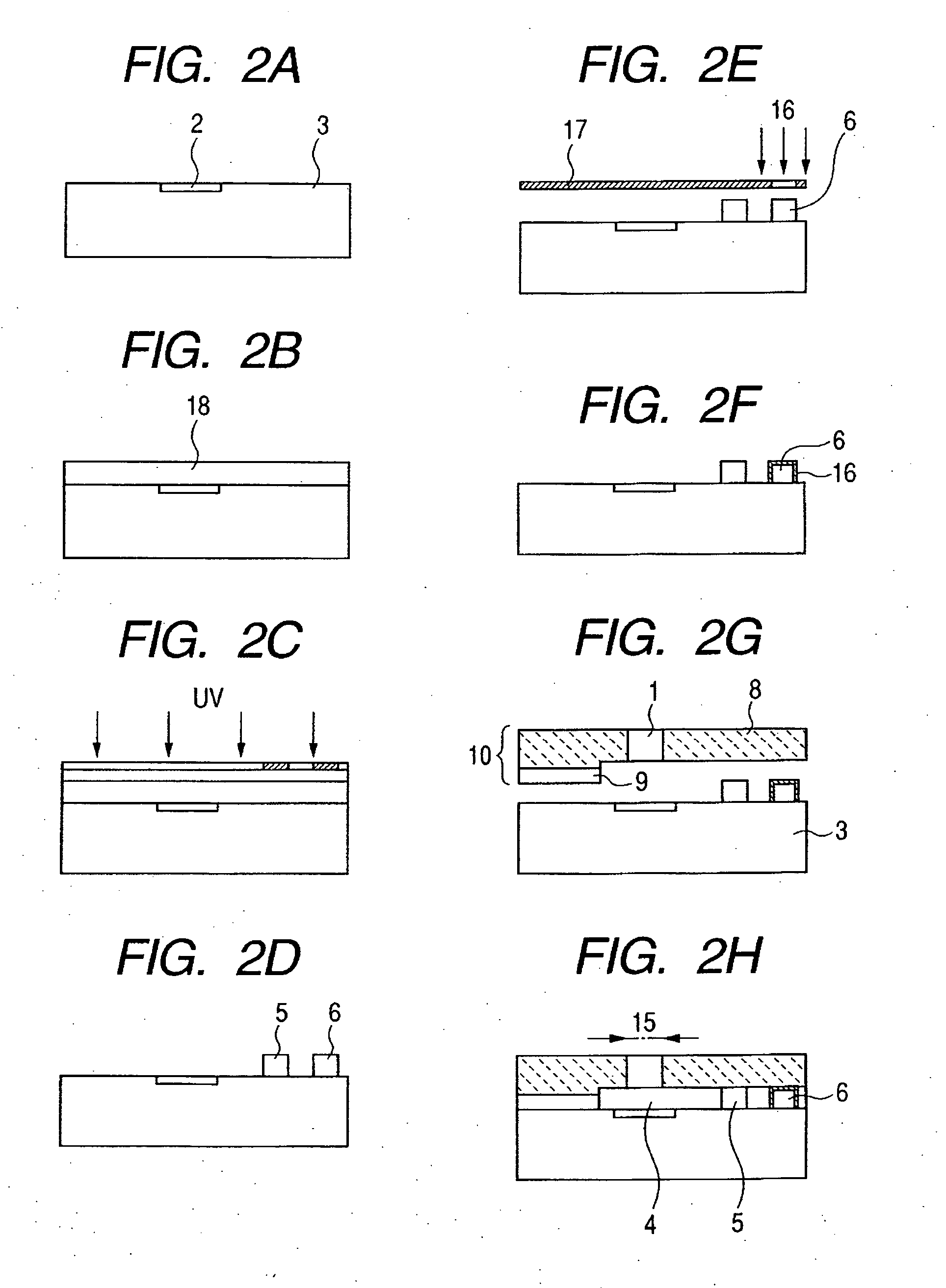
[0048]FIGS. 6A to 6H are typical perspective views showing a method of manufacturing the ink jet recording head shown in FIG. 1 in the order of steps.

[0049] The protruding portions 5 can be formed simultaneously with the protruding portions 6 at the step shown in FIG. 6C. The details of the forming step are as described with reference to FIG. 5C in Embodiment 1. Thereafter, at the step shown in FIG. 6D, the water repelling process is effect...

embodiment 3

[0057]FIGS. 8A to 8H are typical perspective views showing another method of manufacturing the ink jet recording head shown in FIG. 1 in the order of steps.

[0058] First, as shown in FIG. 8A, a desired plurality of liquid discharging energy generating elements 2 such as electro-thermal converting members were provided on the semiconductor substrate 3. Then, as shown in FIG. 8B, AZ-4903 (produced by Hoechst Co., Ltd.) as positive type photosensitive resin was applied onto the semiconductor substrate 3 by a spin coat method so that the film thickness thereof might be 30 μm, and prebaking was effected in an oven at 90° C. for 40 minutes to thereby form a photosensitive resin layer 18. Pattern exposure was effected on this photosensitive resin layer 18 with an exposure amount of 800 mj / cm2 by a mask aligner PLA-501 (produced by Canon Inc.) through a pattern mask (not shown), whereafter development was effected by the use of a sodium hydroxide water solution of 0.75 wt. %. Thereafter, af...


PUM


Abstract

An ink jet recording head which makes it difficult for any bubble and solid matter such as dust existing in supplied ink to reach the vicinity of a nozzle includes a plurality of energy generating elements 2 for generating energy for discharging the ink, a plurality of discharge ports 1 provided at locations opposed to the respective energy generating elements to discharge the ink there through, a plurality of ink flow paths 4 communicating with the respective discharge ports 1, and an ink supplying port 7 for supplying the ink to the plurality of ink flow paths 4. Water repellent protruding portions 6 having their surfaces formed of a material having surface energy smaller than the interfacial energy between them and the ink are provided upstream of the discharge ports 1 with respect to an ink flow direction in which the ink flows from the ink supplying port 7 into the ink flow paths 4 and is discharged from the discharge ports 1.

Description

BACKGROUND OF THE INVENTION [0001] 1. Field of the Invention [0002] This invention relates to an ink jet recording head for discharging ink to thereby effect recording on a recording medium, and a method of manufacturing the same. [0003] 2. Description of Related Art [0004] An ink jet recording head is provided with a discharge port for discharging ink, an ink flow path for supplying the ink to the discharge port, an energy generating element provided in a portion of the ink flow path for generating energy for discharging the ink, and an ink supplying port for supplying the ink to the ink flow path. [0005] The ink jet recording head in recent years is very small in the discharge port (hereinafter referred to as the “nozzle”) in order to realize the recording of an image of high quality and a higher speed. In contrast, Japanese Patent Application Laid-open No. H06-312506 and Japanese Patent Application Laid-open No. H05-124206 disclose a construction in which a pillar-shaped dust cat...

Claims


Application Information

Patent Timeline
IPC IPC(8): B41J2/05
CPCB41J2/14145B41J2/1603B41J2/1606B41J2/1631B41J2/1632B41J2/1634B41J2/17563B41J2002/14403
Inventor SHINOHARA, AKINORIISHIZAKI, AKEMI
Owner CANON KK
Why Eureka
Try Eureka