Solid electrolytic capacitor and method of manufacturing solid electrolytic capacitor cathode material

Active Publication Date: 2006-09-28
SANYO ELECTRIC CO LTD
View PDF3 Cites 14 Cited by
  • Summary
  • Abstract
  • Description
  • Claims
  • Application Information

AI Technical Summary

Benefits of technology

[0010] It is an object of the present invention to lower ESR of a solid electrolytic capacitor s

Problems solved by technology

Therefore, a problem in the solid electrolytic capacitor described above has been that when the specific resistance of the electrolyte layer and the cathode and the contact resistance between the electrolyte layer and the cathode become large,

Method used


Image

  • Solid electrolytic capacitor and method of manufacturing solid electrolytic capacitor cathode material
  • Solid electrolytic capacitor and method of manufacturing solid electrolytic capacitor cathode material

Examples


Example

EXAMPLE 1

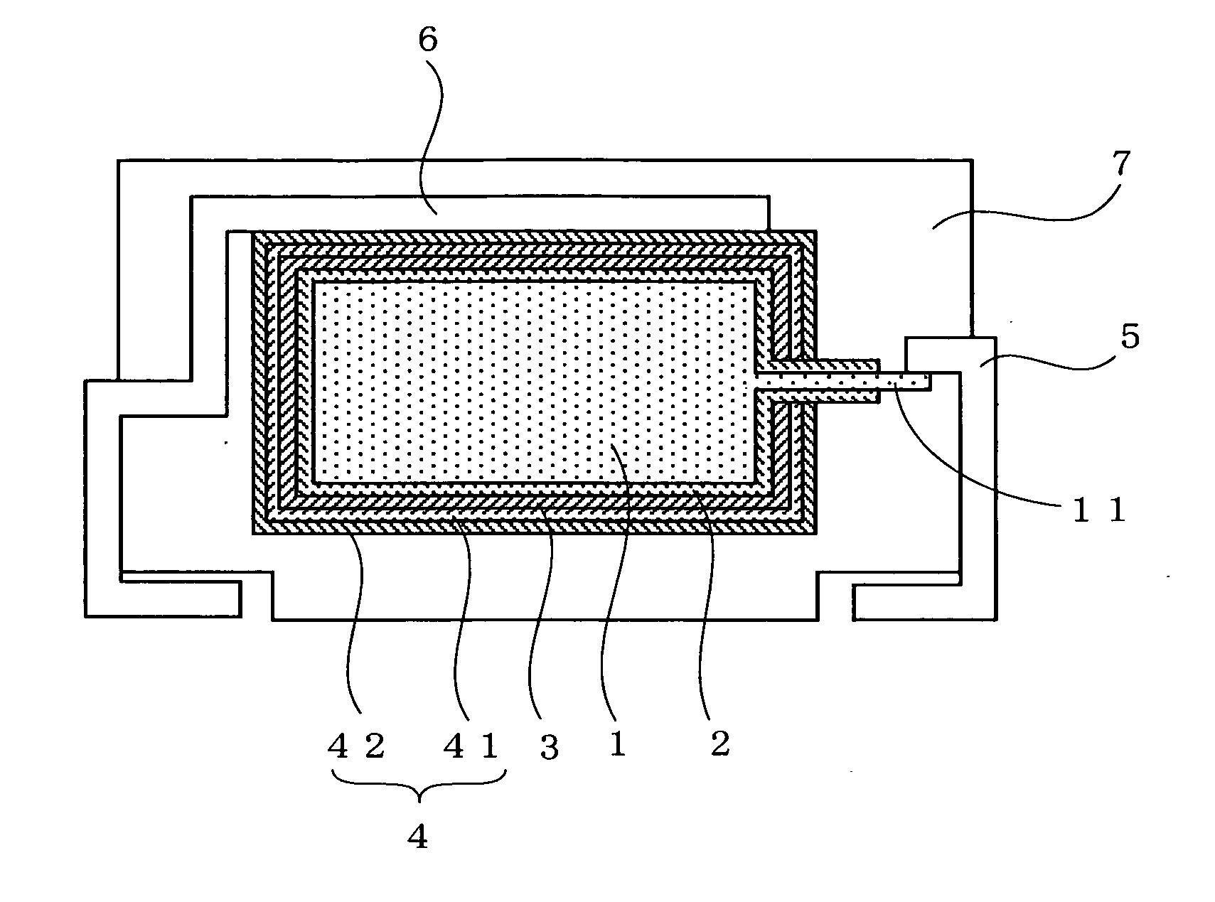
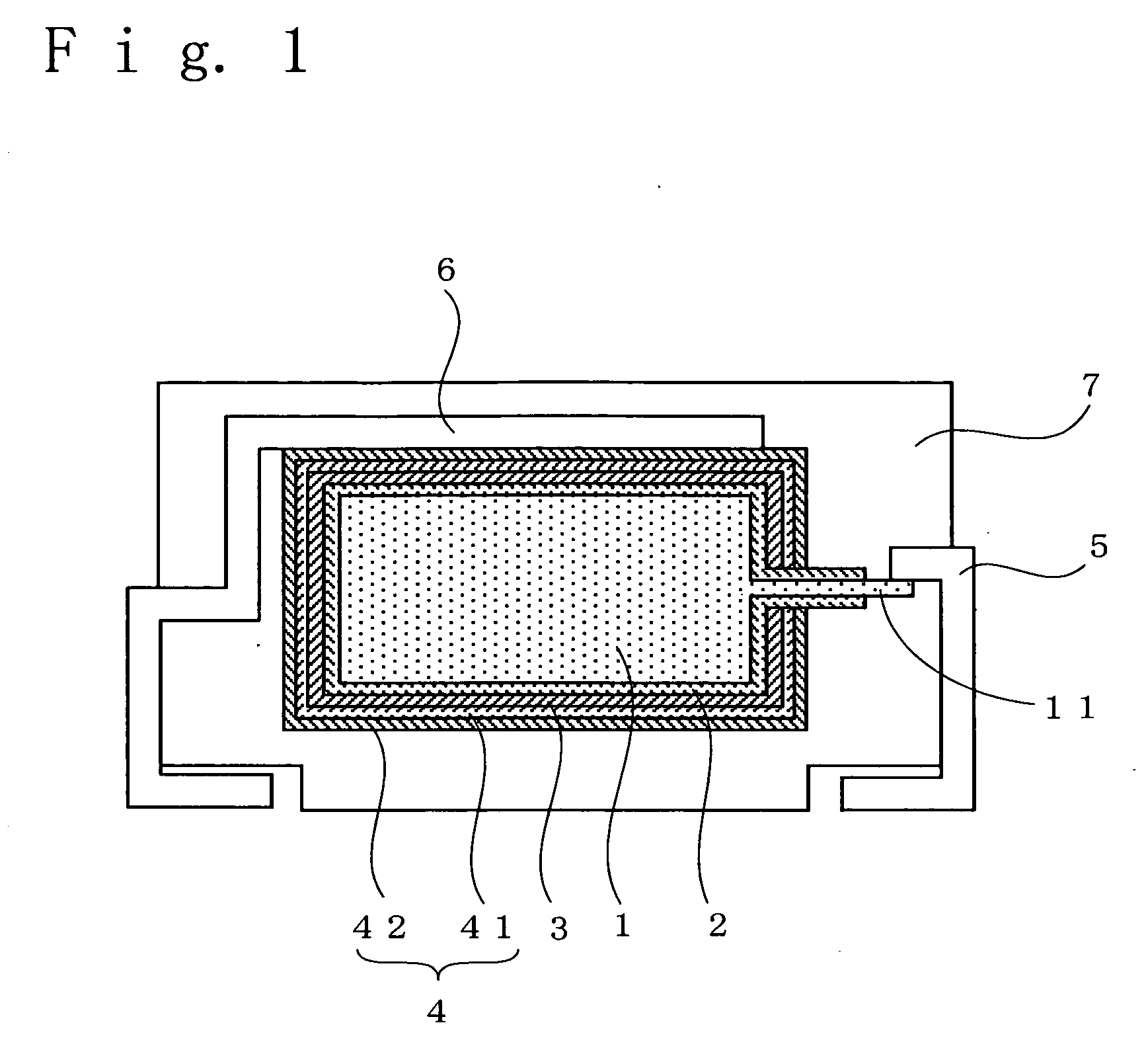
[0033] In a solid electrolytic capacitor of Example 1, a porous sintered body of tantalum formed by sintering tantalum particles was used for an anode 1 and a lead 11 was led out of the anode 1.

[0034] The anode 1 was anodized by applying a voltage of about 10 V for about 10 hours in 0.5 wt % phosphoric acid solution having a temperature of about 60° C. to form a dielectric layer 2 of tantalum oxide on the surface of the anode 1, and an electrolyte layer 3 of polypyrrole was formed on the dielectric layer 2 by electrolytic polymerization, and so on.

[0035] Then, a cathode 4 depositing a carbon layer 41 and a silver layer 42 on the electrolyte layer 3 was formed.

[0036] The carbon layer 41 was formed on the electrolyte layer 3 as follows. After soaking carbon particles in a silver nitrate aqueous solution, the carbon particles were heat-treated at 160° C. for 30 minutes. This operation was repeated 3 times to obtain coated carbon particles in which the surface of carbon par...

Example

EXAMPLE 2

[0039] The same procedure as in Example 1 was used to fabricate a solid electrolytic capacitor of Example 2, except that a tantalum alloy of which main component is tantalum containing 0.5 wt % of aluminum was used as material for an anode 1.

Example

EXAMPLE 3

[0040] In Example 3, coated carbon particles prepared as follows were used for forming the carbon layer 41. In order to prepare the coated carbon particles in which the surface of carbon particles was coated with tantalum nitride, the carbon particles were heat-treated under nitrogen atmosphere at 300° C. for 30 minutes after being soaked in a solution of tantalum complexes of which ligand was ammonium. A solid electrolytic capacitor of Example 3 was fabricated in the same manner as in Example 1 except for the coated carbon particles.


PUM


Abstract

A solid electrolytic capacitor comprising: an anode of valve metal or of an alloy of which main component is the valve metal; a dielectric layer formed by anodizing the anode; an electrolyte layer formed on the dielectric layer; and a cathode formed on the electrolyte layer; wherein the cathode comprises a carbon layer containing coated carbon particles in which at least a part of the surface of carbon particles is coated with metal and/or metal compound having higher conductivity than carbon.

Description

RELATED APPLICATION [0001] The priority application number Japanese Patent Application 2005-82876 upon which this application is based is hereby incorporated by reference. BACKGROUND OF THE INVENTION [0002] 1. Field of the Invention [0003] The present invention relates to a solid electrolytic capacitor and to a method of manufacturing cathode material of a cathode for said solid electrolytic capacitor, which comprises: an anode of valve metal or of an alloy of which main component is the valve metal; a dielectric layer formed by anodizing said anode; an electrolyte layer formed on said dielectric layer; and a cathode formed on said electrolyte layer. More particularly, a feature of the invention is to improve cathode material used for a cathode of a solid electrolytic capacitor and to lower equivalent series resistance of the solid electrolytic capacitor. [0004] 2. Description of the Related Art [0005] Conventionally, solid electrolytic capacitors have been commonly used for a varie...

Claims


Application Information

Patent Timeline
IPC IPC(8): H01G9/00
CPCH01G9/012H01G9/042H01G9/0425
Inventor TAKE, HIROYOSHIYANO, MUTSUMIKIMOTO, MAMORU
Owner SANYO ELECTRIC CO LTD
Why Eureka
Try Eureka