Temperature sensor

a technology of temperature sensor and sensor element, which is applied in the field of temperature sensor, can solve the problems of harsh environment of the cooling system of the automotive engine, and achieve the effect of improving thermal or heat transfer to the sensor element and improving thermal transfer

Active Publication Date: 2006-09-28
STONERIDGE INC
View PDF8 Cites 29 Cited by
  • Summary
  • Abstract
  • Description
  • Claims
  • Application Information

AI Technical Summary

Benefits of technology

[0010] In addition, the temperature sensor may include a sensor tip having a configuration conducive to improving thermal transfer from the medium through the sensor tip to the sensor element. A thermally conductive material may also be used to improve the thermal or heat transfer to the sensor element.
[0011] In a further embodiment, the sensor includes a plurality of threads located on an outer surface of the housing for use in mounting or securing the temperature sensor. In some instances, application of a microencapsulated thread compound helps secure the temperature sensor in place.

Problems solved by technology

An automotive engine cooling system is a harsh environment due to the corrosive behavior of the fluids used and the temperature extremes.

Method used


Image

  • Temperature sensor
  • Temperature sensor
  • Temperature sensor

Examples


Embodiment Construction

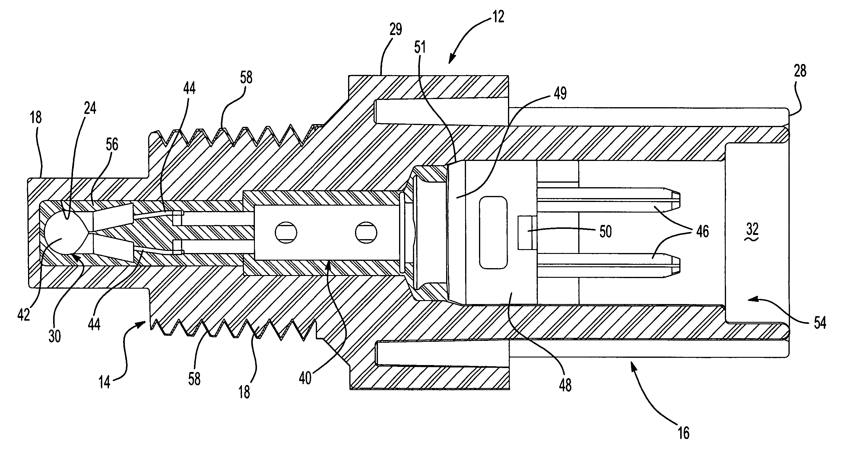
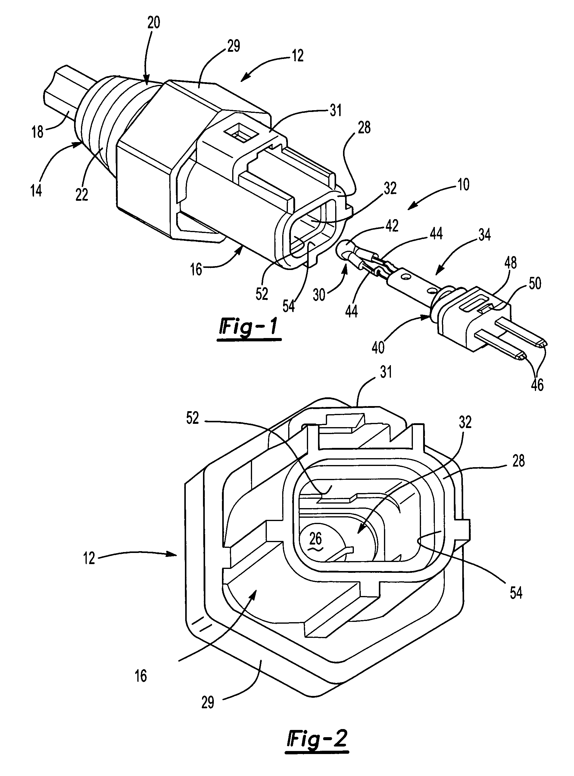
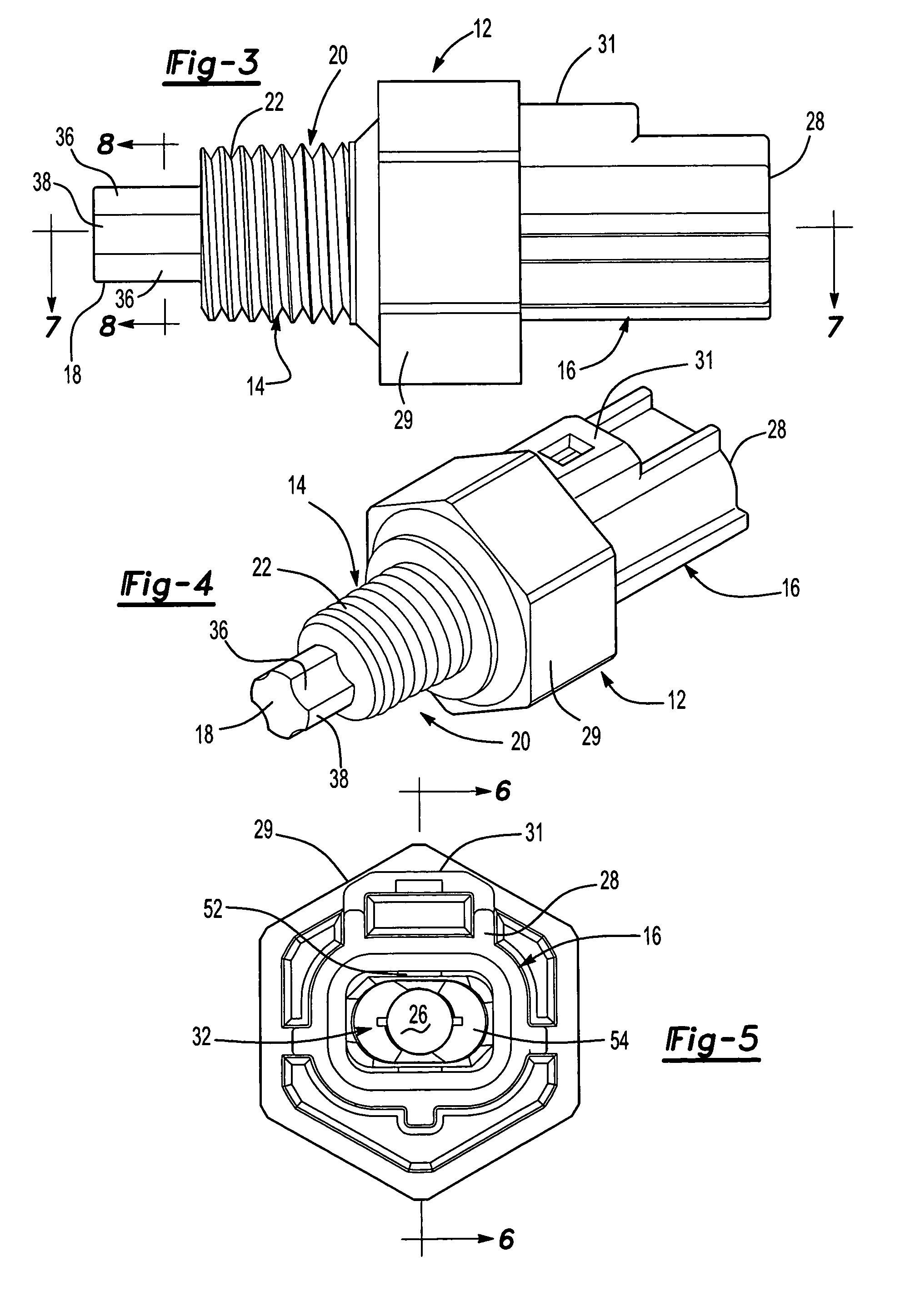
[0026]FIGS. 1-9 illustrate a temperature sensor 10 according to one embodiment of the present invention. The temperature sensor 10 includes a one-piece housing 12. The one-piece housing 12 includes a sensor portion 14 and a connector portion 16. The sensor portion 14 includes a sensor tip 18 located at an end of the housing 12 opposite the connector portion 16. The sensor portion further includes a mounting or attachment assembly, seen generally at 20, used to secure the temperature sensor 10 such that the sensor tip 18 is located in and senses the temperature of a selected fluid, for example, coolant located in an engine cooling system of an automotive vehicle. As shown in the embodiment of FIG. 1, the mounting or attachment assembly 20 includes a plurality of tapered threads 22, commonly referred to as NPT, located on an outer surface of the housing 12. The threads 22 made with corresponding threads located in a mounting aperture. The housing 12 also includes a drive portion, seen...


PUM

PropertyMeasurementUnit
temperatureaaaaaaaaaa
thermal transferaaaaaaaaaa
thermally conductiveaaaaaaaaaa

Abstract

A temperature sensor used to monitor coolant and an automobile coolant system. The temperature sensor includes a one-piece housing having a sensor portion and a connector portion. A sensor assembly, including a sensor having a pair of terminals connected thereto is disposed within the housing. The sensor portion includes a sensor tip having a configuration conducive to improving thermal transfer from the coolant through the sensor tip to the sensor. A thermally conductive material may also be used to improve thermal or heat transfer to the sensor.

Description

CROSS-REFERENCE TO RELATED APPLICATIONS [0001] Not Applicable. BACKGROUND OF THE INVENTION [0002] 1. Field of the Invention [0003] The present invention relates generally to a temperature sensor; and more specifically, to a coolant temperature sensor that monitors the temperature of a cooling fluid used with an internal combustion engine. [0004] 2. Description of Related Art [0005] Currently, automotive vehicles use an internal combustion engine as a power plant for the vehicle. Internal combustion engines generate friction, which correspondingly generates heat. To dissipate the heat and maintain proper engine temperature, many automotive vehicles utilize a liquid cooling system. The liquid cooling system operates by circulating coolant through the engine to collect the heat and then through a radiator to dissipate it. One component of the cooling system includes a cool and temperature sensor that provides coolant temperature feedback or information to the vehicle operator. In addit...

Claims


Application Information

Patent Timeline
Patent Type & Authority Applications(United States)
IPC IPC(8): G01K1/00G01K7/00G01K13/00
CPCG01K1/16G01K13/02G01K2205/00G01K1/08G01K7/02
Inventor GADONNIEX, DENNIS M.WHARTON, STEVENPHILBIN, JEFFREY L.
Owner STONERIDGE INC
Why Eureka
Try Eureka