Electroacoustic transducer

a transducer and electroacoustic technology, applied in the field of electroacoustic transducers, can solve the problems of linear and non-linear distortion, distorted distribution of magnetic field along the gap, etc., and achieve the effect of avoiding such inhomogeneities in magnetic field, reducing stray magnetic field, and reducing sensitivity

Inactive Publication Date: 2006-09-28
HANSEN KAJ BORGE +1
View PDF7 Cites 25 Cited by
  • Summary
  • Abstract
  • Description
  • Claims
  • Application Information

AI Technical Summary

Benefits of technology

[0006] Such inhomogeneities in the magnetic field are avoided with the invention, whereby a cleaner output from the transducer is obtained, whether the transducer is a microphone or a speaker transducer. The magnetic field is stronger than in the known transducers, whereby the transducers can be made even smaller and still have the same sensitivity, which will be appreciated by the manufacturers of e.g. mobile telephones. Further, due to the magnetic circuit the transducer will have a reduced stray magnetic field relative to the traditional transducers.

Problems solved by technology

If the inner and outer members defining the gap are not perfectly coaxial, the gap will not have a uniform width resulting in a distorted distribution of the magnetic field along the gap.
A coil carrying electric currents at audio frequencies in such a distorted magnetic field will tend not to move in a linear movement but to tilt, which causes linear and non-linear distortion.

Method used


Image

  • Electroacoustic transducer
  • Electroacoustic transducer
  • Electroacoustic transducer

Examples


Embodiment Construction

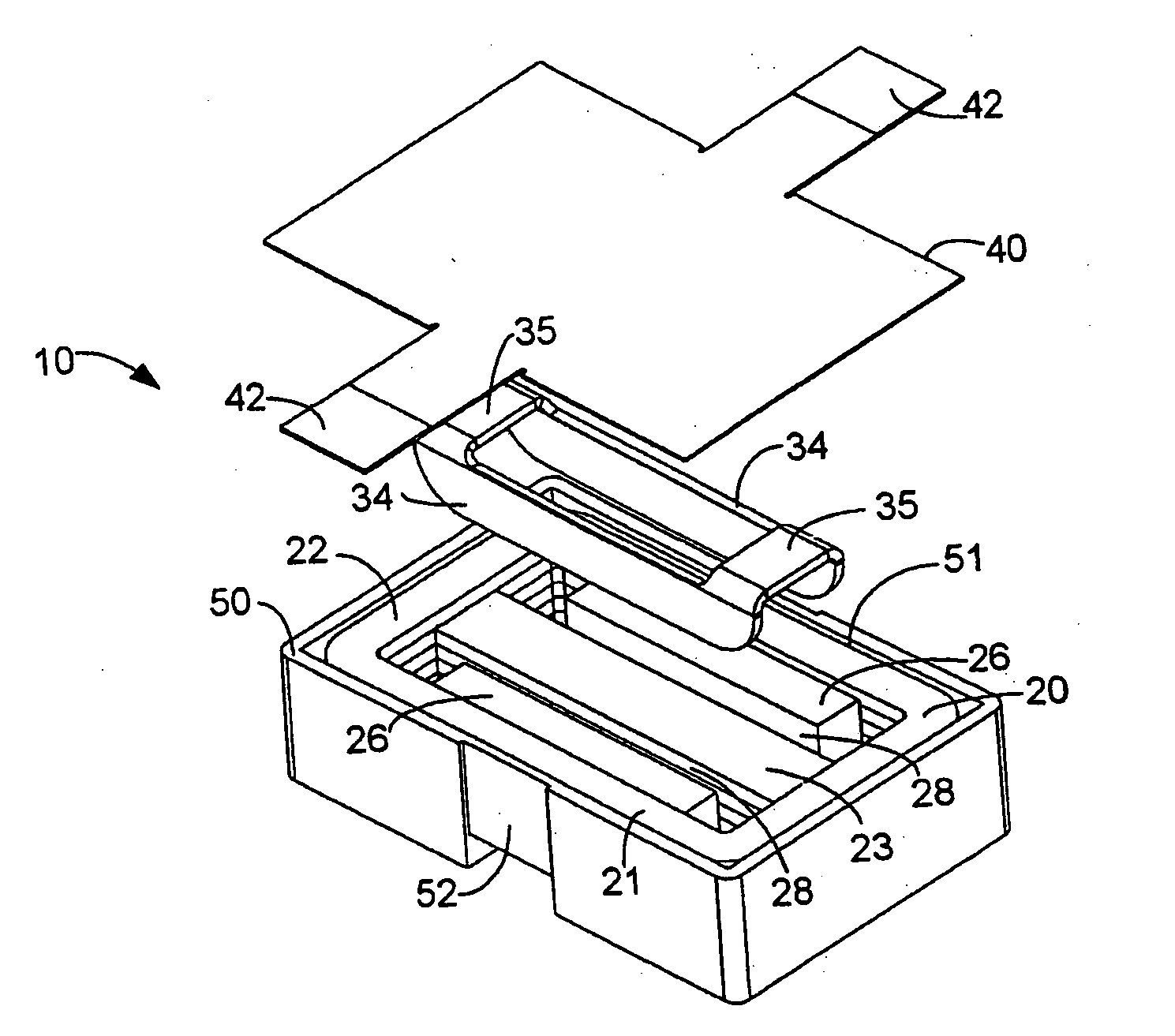
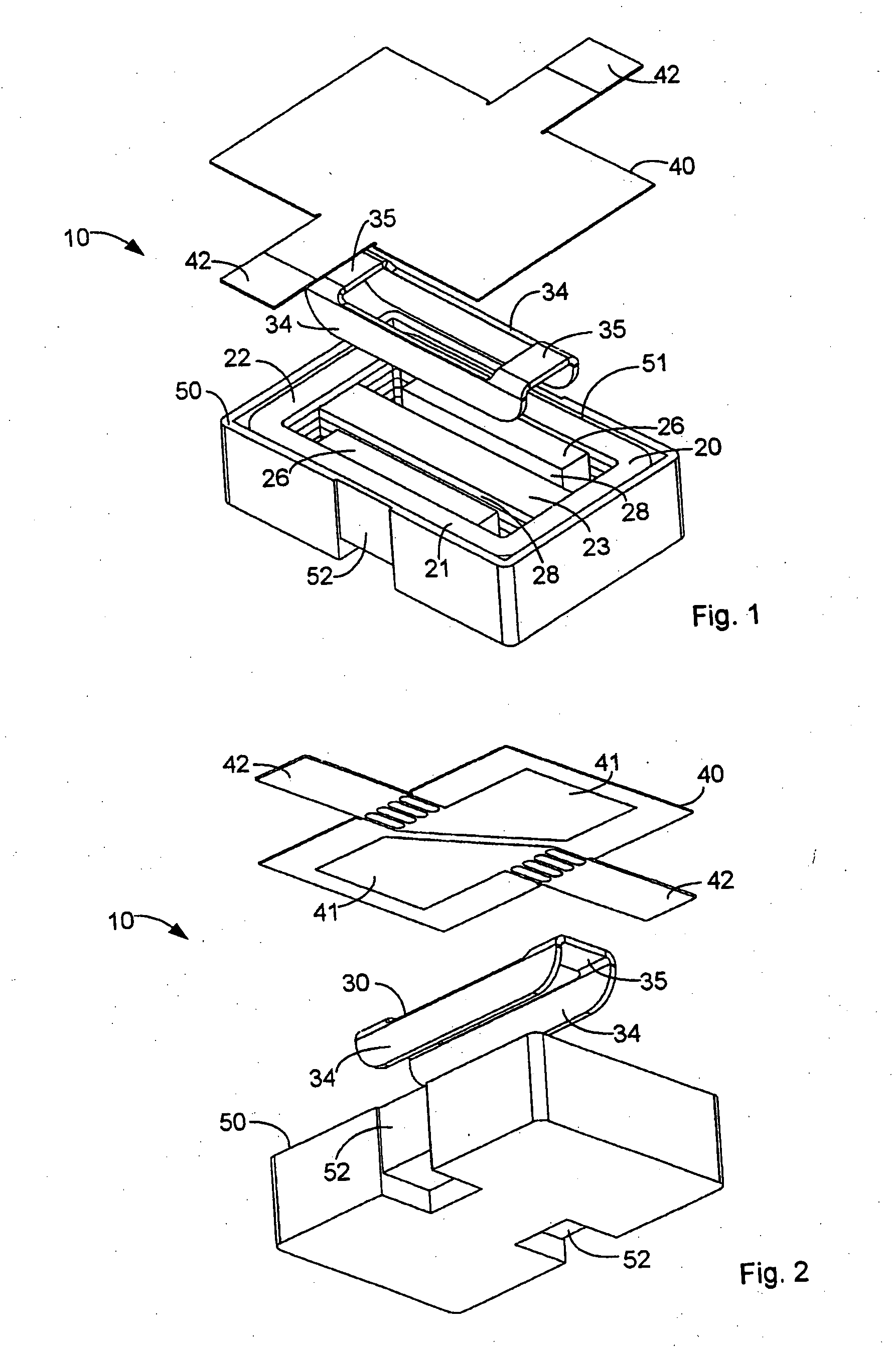
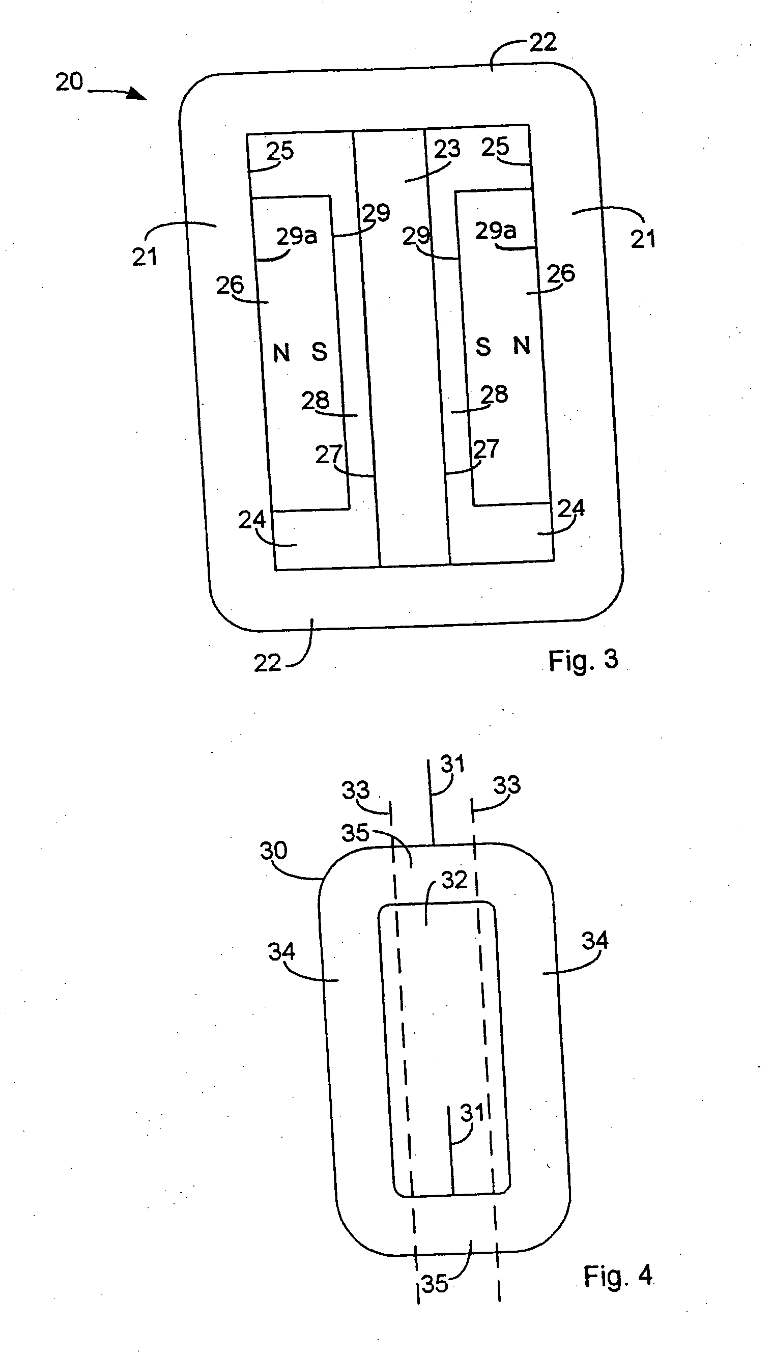
[0012]FIGS. 1 and 2 show an electrodynamic transducer 10 with its main components: a magnetic circuit 20, a coil 30 and a diaphragm 40. FIG. 3 also shows the magnetic circuit 20.

[0013] As is best seen in FIG. 3, the magnetic circuit 20 has two long legs 21 and two short legs 22 connected at their ends to form a ring of generally rectangular shape. A middle leg 23 interconnects the two short legs 22 dividing the internal of the rectangular ring into two rectangular openings 24. The two long legs 21, the two short legs 22 and the middle leg 23 of the magnetic circuit are of a magnetically soft material preferably having a high magnetic saturation value. The surfaces of the two long legs 21 and of the middle leg 23 facing towards the openings 24 are generally plane and define a gap therebetween. On the plane side 25 of each of the long legs 21 facing the opening 24 is a magnet 26 attached to the sides 25. The magnets 26 each have a magnetic pole surface attached to the long leg and th...


PUM

PropertyMeasurementUnit
angleaaaaaaaaaa
magnetic fieldaaaaaaaaaa
electrically conductiveaaaaaaaaaa

Abstract

An electroacoustic transducer includes a magnetic circuit of a magnetically conductive material with a pair of opposed surfaces defining a gap therebetween. The magnetic circuit includes a magnet inducing a magnetic field in the gap, the magnet having a surface constituting one of the opposed surfaces. The magnetic circuit further includes a diaphragm and a coil having electrically conducting paths secured to the diaphragm. The coil has portions of its paths situated in the gap.

Description

PRIORITY STATEMENT [0001] This non-provisional application is a continuation of application Ser. No. 10 / 057,848, filed Jan. 25, 2002, which claims priority under USC 119(a) on Danish Patent Application No. PA 2001 00138, filed on Jan. 26, 2001, both of which are herein incorporated by reference in their entirety.FIELD OF THE INVENTION [0002] The present invention relates to electroacoustic transducers, and in particular to electrodynamic transducers with a diaphragm carrying a coil movable in a magnetic field. BACKGROUND OF THE INVENTION [0003] Electroacoustic transducers, and in particular electrodynamic transducers, are widely used in telecommunications equipment such as wired and mobile telephones, where small size is a requirement. Traditional electrodynamic microphones and speaker transducers used in e.g. mobile telephones are rotational symmetric and have a circular disc or ring shaped permanent magnet, which is magnetised in the axial direction of the magnet. A magnetic circu...

Claims


Application Information

Patent Timeline
Patent Type & Authority Applications(United States)
IPC IPC(8): H04R9/06H01F7/06H01F27/30H01F41/071H01F41/10H04R7/04H04R7/12H04R9/02H04R9/04H04R9/08
CPCH01F7/066H01F27/306H01F41/10H01F2041/0662H04R7/12H04R9/025H04R9/046H04R9/047H04R9/06H04R9/08H04R2499/11H01F2041/0711
Inventor HANSEN, KAJ BORGEJOHANNSEN, LEIF
Owner HANSEN KAJ BORGE
Why Eureka
Try Eureka