Multipurpose micro-mass sensor of porous cantilever structure

A cantilever beam, multi-purpose technology, applied in the direction of material absorption weighing, instrumentation, weighing, etc., can solve the problems of sensitivity impact, sensitivity reduction, increase measurement cost, etc.

Inactive Publication Date: 2013-03-13
DALIAN UNIV OF TECH
View PDF10 Cites 8 Cited by
  • Summary
  • Abstract
  • Description
  • Claims
  • Application Information

AI Technical Summary

Problems solved by technology

The traditional planar micromass sensor is limited by a single measurement plane, and it is difficult to effectively divide different measurement areas. Therefore, it is mainly used for the measurement of a single substance, and the sensitivity is seriously affected by the measurement position.
The international patent WO 2005 / 043126 A2 proposes a cantilever beam sensor with a rectangular cross-section excited by a single piezoelectric film. Since the stiffness-to-mass ratio of the cantilever beam with a rectangular cross-section is fixed and the detection area is a single plane, it directly results in a single measurement material, which limits its use in Applications in gas / liquid concentration, tiny particle measurement, etc.
U.S. Patent US6722200 proposes a silicon material sensor that can measure the mass of a single atom. The sensitivity of the edge position of the cantilever beam is significantly lower than that of the center position. Since the sensor mainly relies on adsorption to fix the measured atoms, the adsorption position will directly affect the measurement. result
U.S. Patent US 6389877 B1 and domestic patent CN1250156A use single-head and double-head cantilever structures to measure frequency. Although the measurement area is increased by increasing the cantilever area, the system effective mass M of the cantilever beam is also increased. e , which is not conducive to the improvement of sensor sensitivity, and there is a contradiction between the increase of the detection area and the decrease of sensitivity
Recently, the domestic invention patent publication number CN 1609555A proposes to measure the quality by measuring the displacement difference of the vibrator with the probe adsorbed on it, but a complex optical displacement measurement system is required, which increases the measurement cost
Although the sensor described in the first issue of "Optical Precision Engineering" in 2012 "Design of micromass sensor based on trough cantilever beam structure" effectively improves the sensitivity of the sensor, the sensitivity is easily affected by the measurement position
[0003] A comprehensive analysis found that due to the limitation of its own structure, the planar mass sensor has the weakness of small measurable area, single measurement type and sensitivity easily affected by the measurement position, which seriously affects its scope of application

Method used


Image

  • Multipurpose micro-mass sensor of porous cantilever structure
  • Multipurpose micro-mass sensor of porous cantilever structure
  • Multipurpose micro-mass sensor of porous cantilever structure

Examples


Embodiment 1

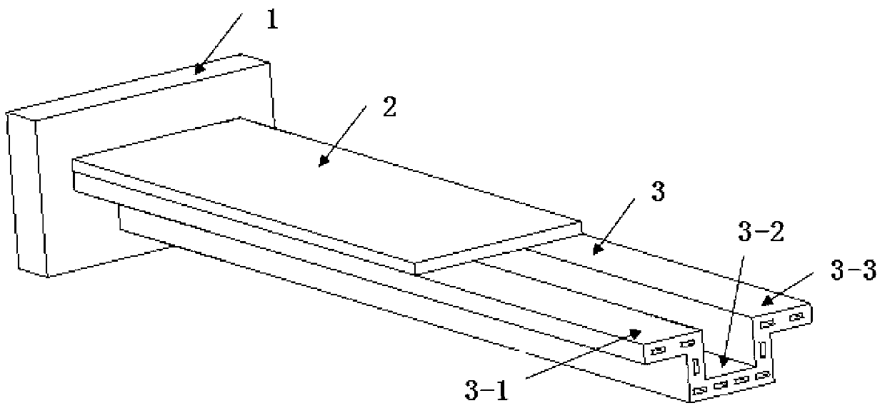
[0040] figure 1 A structural schematic diagram of a multipurpose micromass sensor with a porous cantilever beam structure is given. Wherein, the lower surface of the piezoelectric film 2 is connected to the upper surface of the porous cantilever beam 3, one section of the piezoelectric film 2 and the porous cantilever beam is connected to the fixed block 1, and the other end is suspended to form a composite cantilever beam structure. There is no gap connection between the piezoelectric film 2 and the porous cantilever beam, and the length of the piezoelectric film 2 is smaller than the porous cantilever beam structure. Bounded by the free end of the piezoelectric film 2, the composite cantilever beam structure is divided into two parts: the composite layer and the extension layer. Both the flange surface of the extension layer and the inner surface of the square groove can be used as the detection area to detect the quality of the measured object. The porous cantilever beam ...

Embodiment 2

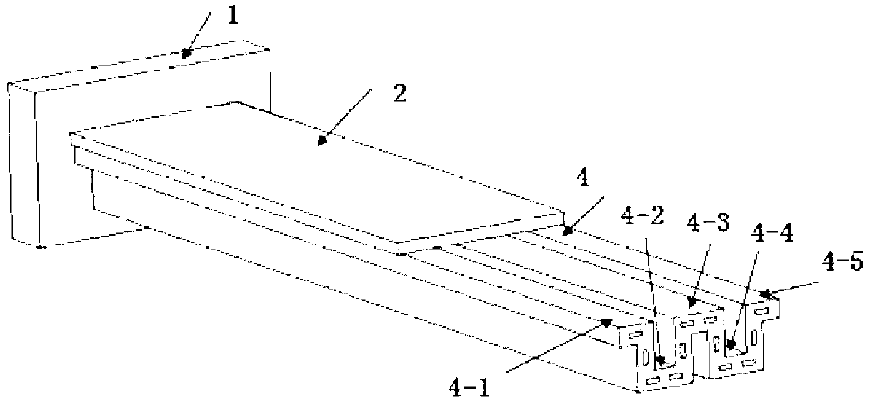
[0050] image 3 It is a structural schematic diagram of Embodiment 2 of a multipurpose micromass sensor with a porous cantilever beam structure in the present invention. On the basis of Embodiment 1, the porous cantilever beam 3 is replaced by the double-groove porous cantilever beam 4, and the number of its measurable areas is further expanded to 5, which are respectively areas 4-1, 4-2, and 4-3 , 4-4, 4-5.

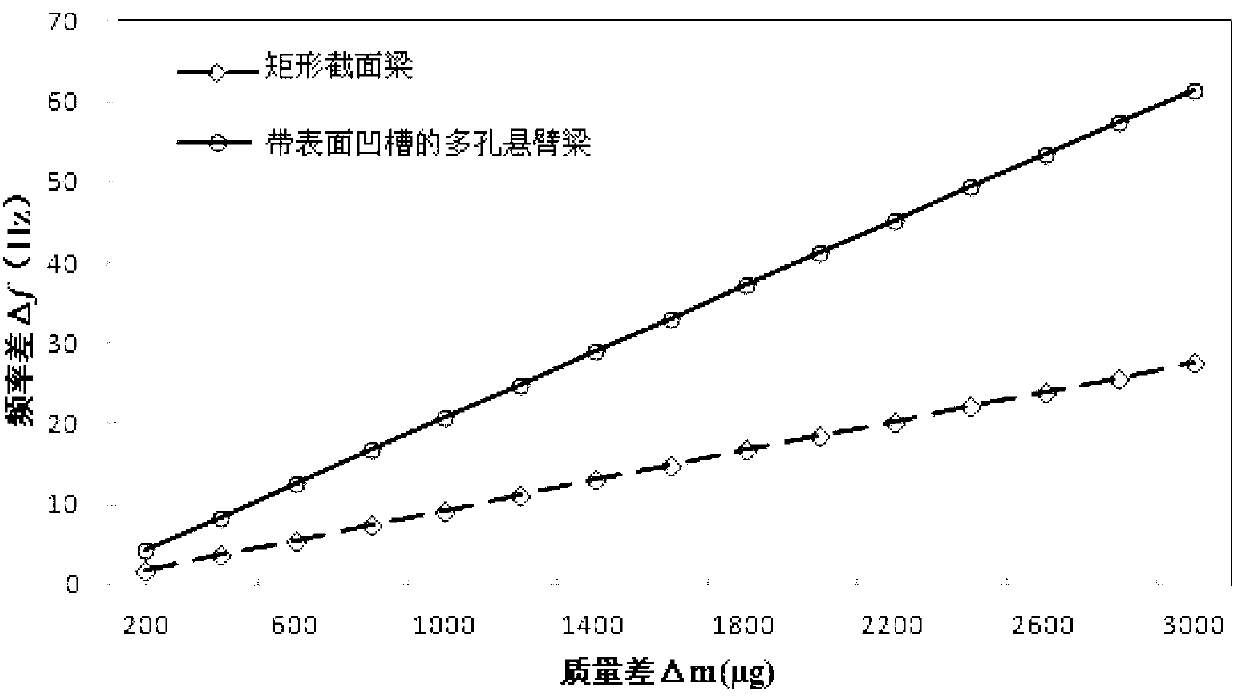
[0051] Figure 4 It is a calculation example of Embodiment 2 of the present invention, and the sensitivity under the same geometric parameters (as shown in Table 1) is compared with the sensitivity of the rectangular cross-section beam structure. According to the definition of sensor sensitivity, the slope of the straight line in the figure is the sensitivity of the corresponding sensor. When the length of the porous cantilever beam is 20.0mm, the sensitivity of the second embodiment is 1.87 times higher than that of the rectangular planar sensor, which effectively im...


PUM

PropertyMeasurementUnit
angleaaaaaaaaaa

Abstract

A multipurpose micro-mass sensor of a porous cantilever structure belongs to the technical field of multipurpose detection sensors. The micro-mass sensor is characterized in that the upper surface of a porous cantilever which is connected with a fixed block is connected with a piezoelectric film, and the areas of the extension part of the cantilever are a plurality of different detection areas with the same sensitivity. The mass of a detected object is accurately calculated according to the data output of the piezoelectric film. The induction of the porous cantilever can realize the following functions: (a) the plurality of detection areas are effectively isolated; (b) the sensitivities of all the positions in the detection areas are highly consistent with each other, so that the position sensitivity of a test result is reduced; and (c) specific examples show that compared with a conventional planar type sensor structure, the multipurpose micro-mass sensor has the sensitivity which can be increased by 187% at most. The multipurpose micro-mass sensor has the characteristics of simplicity in structure, wide measurement scope, good uniformity, high sensitivity and the like, and thus can be widely applied to gas/liquid concentration measurement and the measurement of cell growth and microorganism, such as bacteria or virus and the like.

Description

technical field [0001] The invention relates to a multipurpose micromass sensor with a porous cantilever beam structure, which belongs to the technical field of multipurpose detection sensors and is mainly used for high-precision measurement of various liquid concentrations, cell growth, and microorganisms such as bacteria or virus mass. Background technique [0002] The piezoelectric micromass sensor mainly detects the composition of the substance by measuring the structural resonance frequency change caused by the mass of the substance attached to the surface of the sensor. It has the characteristics of simple structure, fast response, low cost and high precision. It is used in the detection of microorganisms such as bacteria and viruses, It has a wide range of applications in terms of small particles, gas / liquid composition and concentration. The basic principle can be expressed by the following formula, Δf i =-f i Δm / M e , where f i is the i-th resonant frequency of ...

Claims


Application Information

Patent Timeline
Patent Type & Authority Applications(China)
IPC IPC(8): G01G3/16G01N5/02
Inventor 赵剑高仁璟朱传月张延康魏岩张莹
Owner DALIAN UNIV OF TECH
Why Eureka
Try Eureka