Method and apparatus for producing an ion beam from an ion guide

a technology of ion beam and ion guide, which is applied in the field of mass spectrometry utilizing multi-pole ion guides, can solve the problems of ion isolation, fragmentation and analysis, and the high quality of the beam is usually achieved at the expense of instrument sensitivity, so as to achieve the same sensitivity, higher mass resolution, and the effect of high instrument sensitivity

Inactive Publication Date: 2006-07-27
SCI & ENG SERVICES
View PDF8 Cites 7 Cited by
  • Summary
  • Abstract
  • Description
  • Claims
  • Application Information

AI Technical Summary

Benefits of technology

[0023] In another aspect of the present invention, the divergence of the ion beam originating from the ion guide of the present invention is smaller than in conventional ion beam formation systems, thus resulting in a denser ion beam after shaping the original ion beam into the “parallel” beam to be introduced into the acceleration region of an oa-TOF-MS. This results in a higher instrument sensitivity at the same mass resolution or, if the ion beam is shaped into a more narrow beam results in a higher mass resolution while maintaining the same sensitivity.

Problems solved by technology

Such manipulation of the ions can result in ion isolation, fragmentation and analysis.
However, the high quality of the beam is usually achieved at the expense of instrument sensitivity since many ions are cut off of the beam to make a narrow ion distribution in the phase (i.e., the coordinate and velocity) space.

Method used


Image

  • Method and apparatus for producing an ion beam from an ion guide
  • Method and apparatus for producing an ion beam from an ion guide
  • Method and apparatus for producing an ion beam from an ion guide

Examples


Embodiment Construction

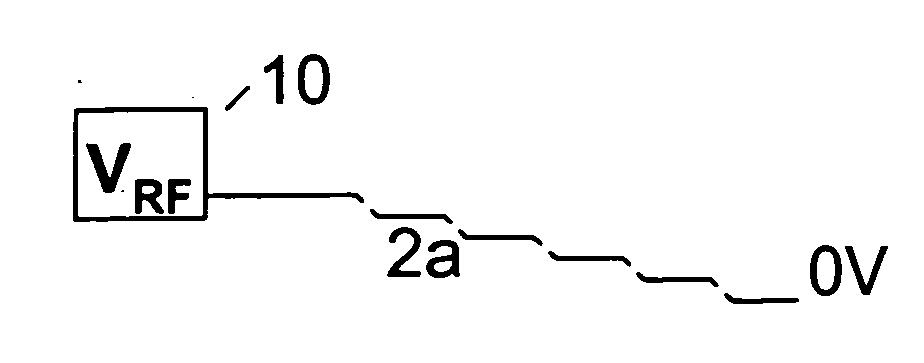
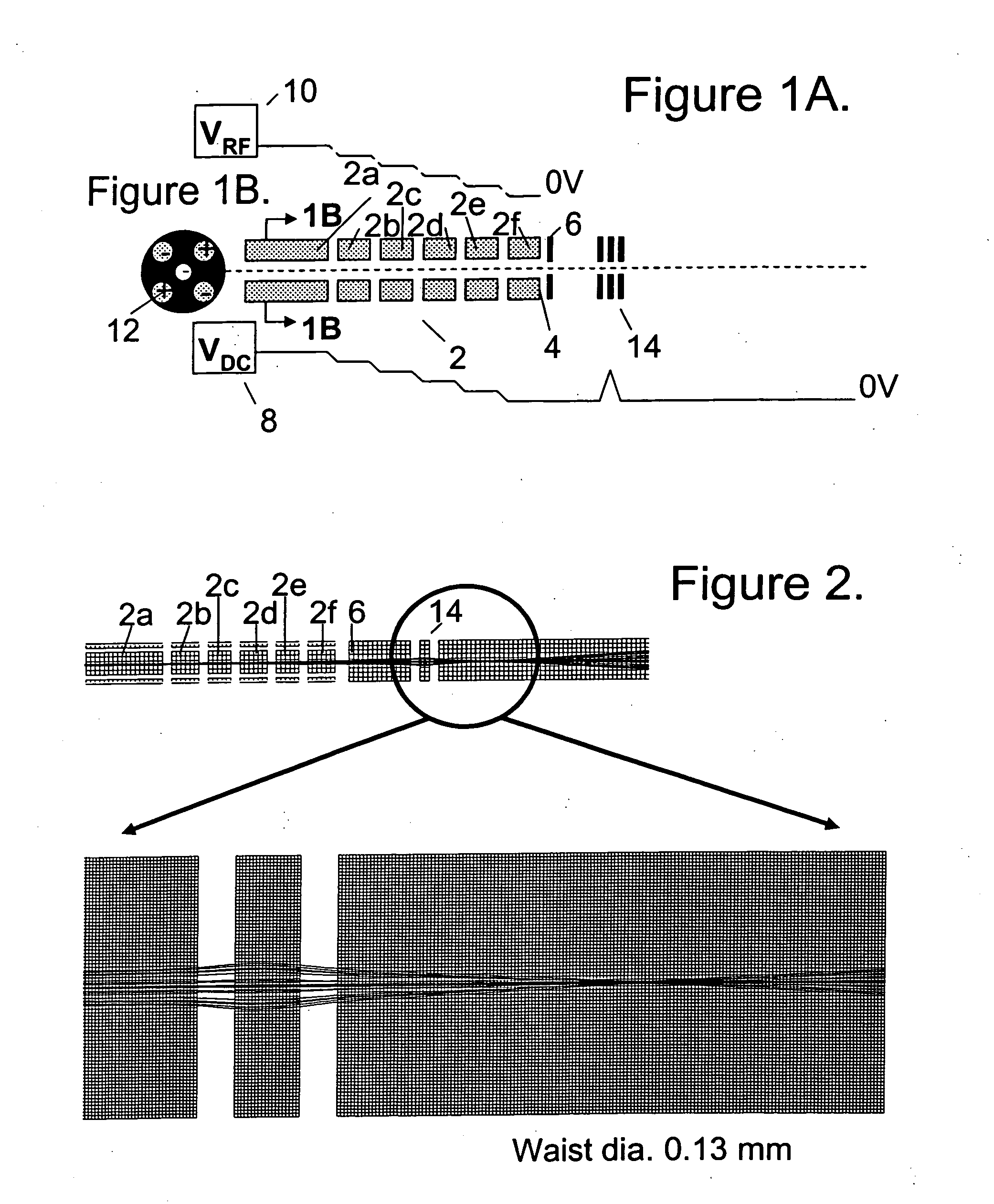
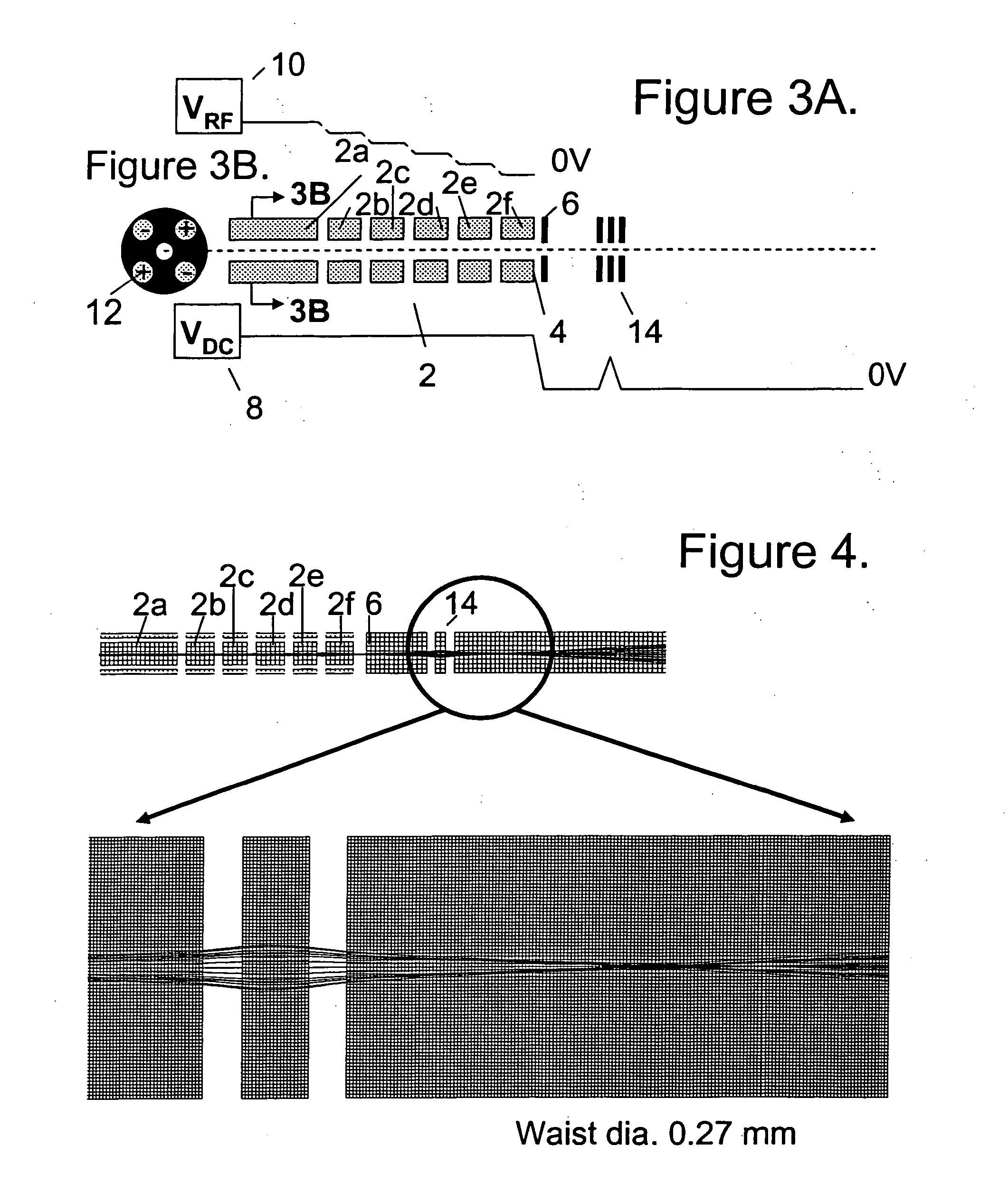
[0043] Referring now to the drawings, wherein like reference numerals designate identical, or corresponding parts throughout the several views, and more particularly to FIG. 1A, FIG. 1A is a schematic according to one embodiment of the present invention for generating an ion beam from an ion guide 2. As such, the system illustrated in FIG. 1A includes an ion guide 2 configured to transmit ions along a longitudinal axis of the ion guide 2 and configured to trap ions in a direction transverse to the longitudinal axis via a radio frequency trapping field. The ion guide includes a segmented set of electrodes 2a, 2b, 2c, 2d, 2e, and 2f spaced along the longitudinal axis and an ion guide 4 exit at the last of the segmented set of electrodes. A radio frequency device 10, as shown in FIG. 1A, is configured to supply the radio frequency trapping field such that a strength of the radio frequency trapping field is progressively reduced toward the ion guide exit. For example, towards the exit 4...


PUM


Abstract

A method and system for producing an ion beam from an ion guide. In the method, ions are introduced into the ion guide, a radio frequency trapping field is generated in the ion guide to confine ions in a direction transverse to a longitudinal axis of the ion guide, a DC potential is generated along the longitudinal axis to direct ion motion along the longitudinal axis, a strength of the radio frequency trapping field is reduced toward an ion guide exit of the ion guide, and the ions are transmitted from the ion guide exit to form the ion beam. In the system, an ion guide is configured to transmit ions in a longitudinal axis of the ion guide and configured to trap ions in a direction transverse to the longitudinal axis via a radio frequency trapping field. The ion guide includes a segmented set of electrodes spaced along the longitudinal axis and an ion guide exit at the last of the segmented set of electrodes. A radio frequency device is configured to supply the radio frequency trapping field such that a strength of the radio frequency trapping field is reduced toward the ion guide exit.

Description

CROSS-REFERENCE TO RELATED APPLICATIONS [0001] This application is related to U.S. Serial application Ser. No. 10 / 441,004 entitled “Method of Ion Fragmentation in a Multipole Ion Guide of a Tandem Mass Spectrometer,” filed on May 20, 2003, the entire contents of which is incorporated herein by reference.BACKGROUND OF THE INVENTION [0002] 1. Field of the Invention [0003] This invention relates in general to mass spectrometry (MS) especially to mass spectrometry utilizing multipole ion guides, and in particular to orthogonal acceleration (oa) time-of-flight (TOF) MS. More specifically, this invention relates to a configuration and a method of using multipole ion guide to transport and focus ions into a mass analyzer. [0004] 2. Description of the Related Art [0005] Over the last decade, mass spectrometry has played an increasingly important role in the identification and characterization of various biochemical compounds in research laboratories and various industries. The speed, specif...

Claims


Application Information

Patent Timeline
Patent Type & Authority Applications(United States)
IPC IPC(8): H01J49/06
CPCH01J49/063
Inventor DOROSHENKO, VLADIMIR M.BERKOUT, VADYM D.
Owner SCI & ENG SERVICES
Why Eureka
Try Eureka